EasyManuals Logo

Tektronix 2465B Service Manual

Tektronix 2465B
536 pages
To Next Page IconTo Next Page
To Previous Page IconTo Previous Page
Page #526 background imageLoading...
Page #526 background image
Product: 2465B/2467B Service
Date:
30 JAN 93 Change Reference: M70831 REV1
DIAGRAM
CHANGES
o
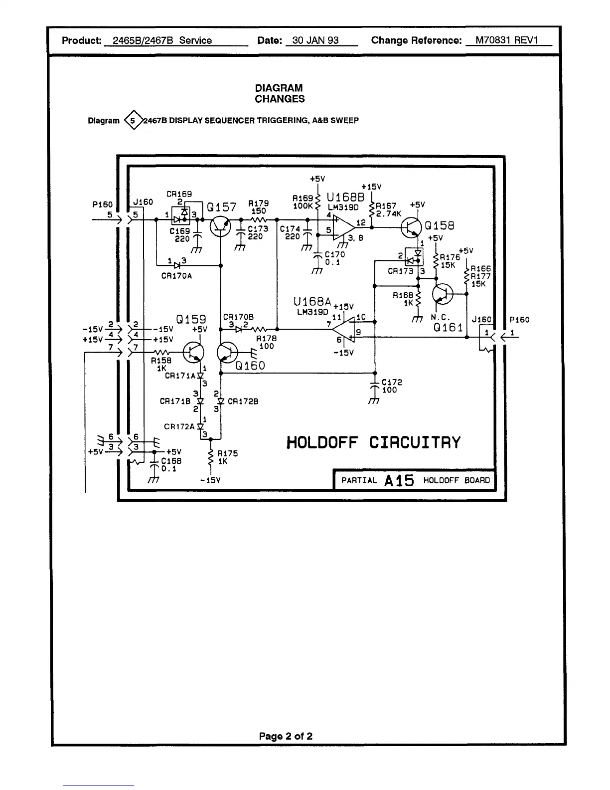
Diagram <5 >2467B DISPLAY SEQUENCER TRIGGERING, A&B SWEEP
P160
5
-15V-f^
+ 15V
v
+5V
J160
CH169
2
»>*
^9-
a4»>f
+5V-3-> >^-
&p
57
C169 _
220 T
1^3
R179
150
-wv-
CR170A
Q159
--15V +5V
- + 15V
~Ici73
T220
CR170B
3 2
U16BA
+15V
LM319D
1D
_WV-
R15B
IK
CR171A
CR171B $
2
CR172A
R178
^100
â– 15V
Q160
2 CR172B
â– +5V
C168
4rC172
100
rh
-15V
HOLDOFF CIRCUITRY
I PARTIAL A 15 HOLDOFF BOARD
Page 2
of
2

Table of Contents

Other manuals for Tektronix 2465B

Questions and Answers:

Question and Answer IconNeed help?

Do you have a question about the Tektronix 2465B and is the answer not in the manual?

Tektronix 2465B Specifications

General IconGeneral
Bandwidth400 MHz
Channels4
Vertical Sensitivity2 mV/div to 5 V/div
Maximum Input Voltage400 V (DC + peak AC)
DisplayCRT
Trigger ModesAuto, Normal, Single
Time Base Range500 ps/div to 0.5 s/div
Rise Time875 ps
Power Supply48 to 440 Hz
Dimensions495 mm

Related product manuals