Tfektronix
COMMtTTED TO
EXCELLENCE
Product: 2465B/2467B Service
MANUAL CHANGE INFORMATION
Date:
30 JAN 93 ~- M71192REV1
Change Reference:
Manual Part No.:
070-6863-00
DESCRIPTION
Product Group 38
EFFECTIVE SERIAL NUMBERS: 2465B B051079 and above
EFFECTIVE SERIAL NUMBERS: 2467B B010885 and above
EFFECTIVE SERIAL NUMBERS: 2467B B050364 and above
BOARD CHANGES
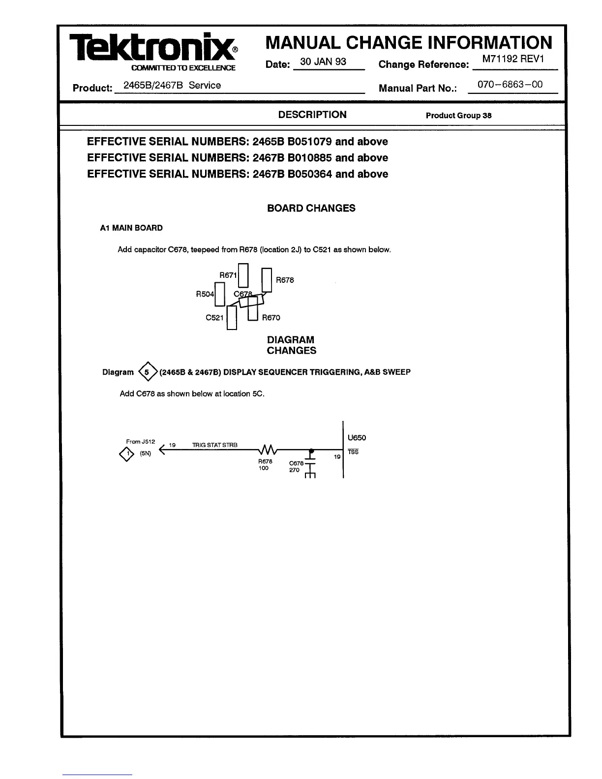
A1 MAIN BOARD
Add capacitor C678, teepeed from R678 (location 2J) to
C521
as shown below.
ffl-
R671
R504 CeTa^-^-'
u
rfn
C521 l_l R670
R678
DIAGRAM
CHANGES
<°><
Diagram <5 >(2465B & 2467B) DISPLAY SEQUENCER TRIGGERING, A&B SWEEP
Add C678 as shown below at location 5C.
From J512
\ (5N)
O
19 TRIG STAT STHB
-vV\r
R678 C678->-
100
270
I
U650
TSS
 Loading...


