Specification—2465B/2467B Service
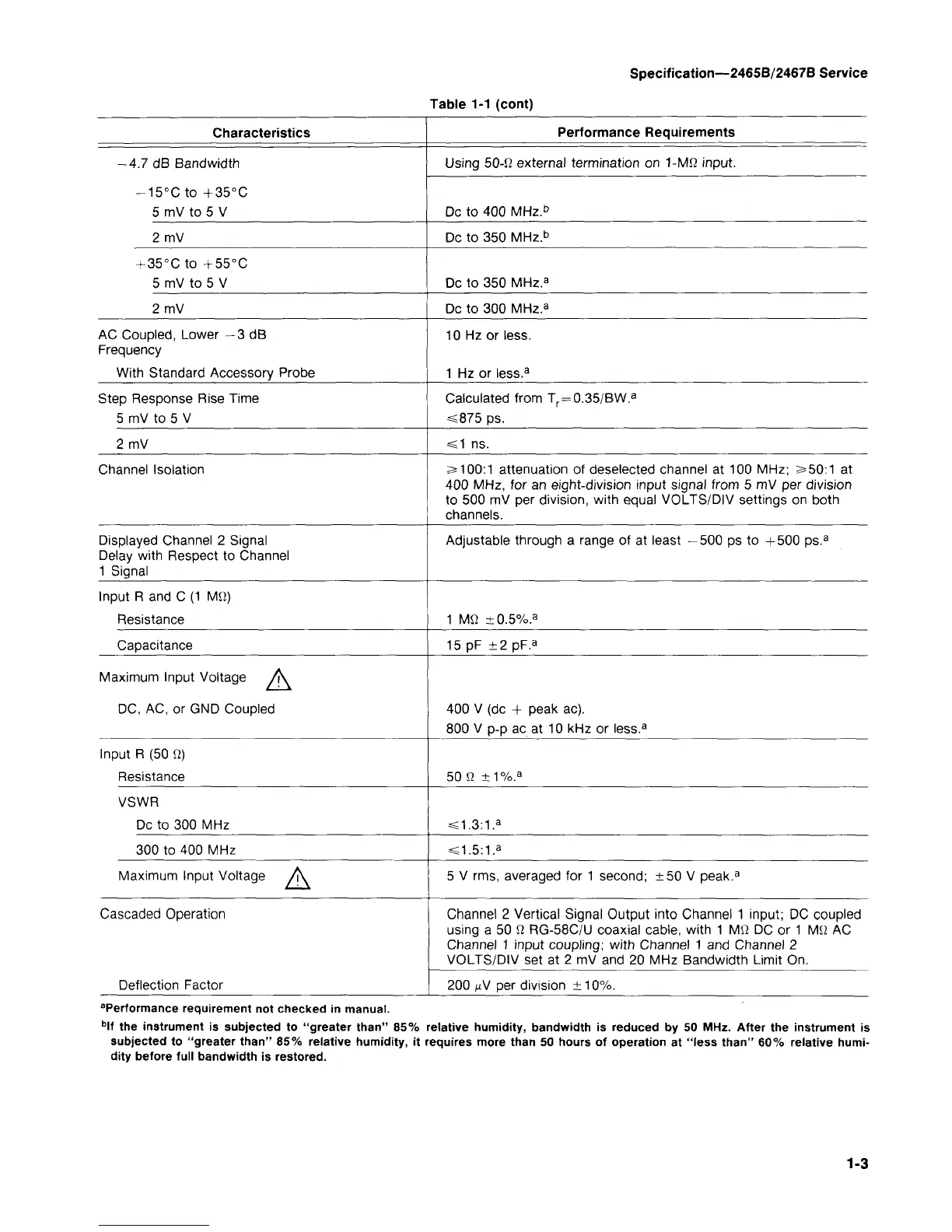
Table 1-1 (cont)
Characteristics
-4.7 dB Bandwidth
-15°C to + 35°C
5 mV to 5 V
2 mV
+ 35°C to +55°C
5 mV to 5 V
2 mV
AC Coupled, Lower -3 dB
Frequency
With Standard Accessory Probe
Step Response Rise Time
5 mV to 5 V
2 mV
Channel Isolation
Displayed Channel 2 Signal
Delay with Respect to Channel
1 Signal
Input R and C (1 MQ)
Resistance
Capacitance
Maximum Input Voltage /K
DC,
AC, or GND Coupled
Input R (50 fi)
Resistance
VSWR
Dc to 300 MHz
300 to 400 MHz
Maximum Input Voltage A.
Cascaded Operation
Deflection Factor
Performance Requirements
Using 50-fl external termination on 1-Mfi input.
Dc to 400 MHz.
b
Dc to 350 MHz.
b
Dc to 350 MHz.
a
Dc to 300 MHz.
a
10 Hz or less.
1 Hz or less.
3
Calculated from T
r
=0.35/BW.
a
<875 ps.
=s1 ns.
^100:1 attenuation of deselected channel at 100 MHz; s»50:1 at
400 MHz, for an eight-division input signal from 5 mV per division
to 500 mV per division, with equal VOLTS/DIV settings on both
channels.
Adjustable through a range of at least —500 ps to +500 ps.
a
1 Mfl ±0.5%.
a
15 pF ±2 pF.
a
400 V (dc + peak ac).
800 V p-p ac at 10 kHz or less.
a
50 a ±1%.
a
<1.3:1.
a
<1.5:1.
a
5 V rms, averaged for
1
second; ±50 V peak.
3
Channel 2 Vertical Signal Output into Channel 1 input; DC coupled
using a 50 fi RG-58C/U coaxial cable, with 1 Mfi DC or
1
Mil AC
Channel 1 input coupling; with Channel 1 and Channel 2
VOLTS/DIV set at 2 mV and 20 MHz Bandwidth Limit On.
200
MV
per division ±10%.
Performance requirement not checked in manual.
b
lf the instrument is subjected to "greater
than"
85% relative humidity, bandwidth is reduced by 50 MHz. After the instrument is
subjected to "greater
than"
85% relative humidity, it requires more than 50 hours of operation at "less
than"
60% relative humi-
dity before full bandwidth is restored.
1-3