Adjustment Procedure—2465B/2467B Service
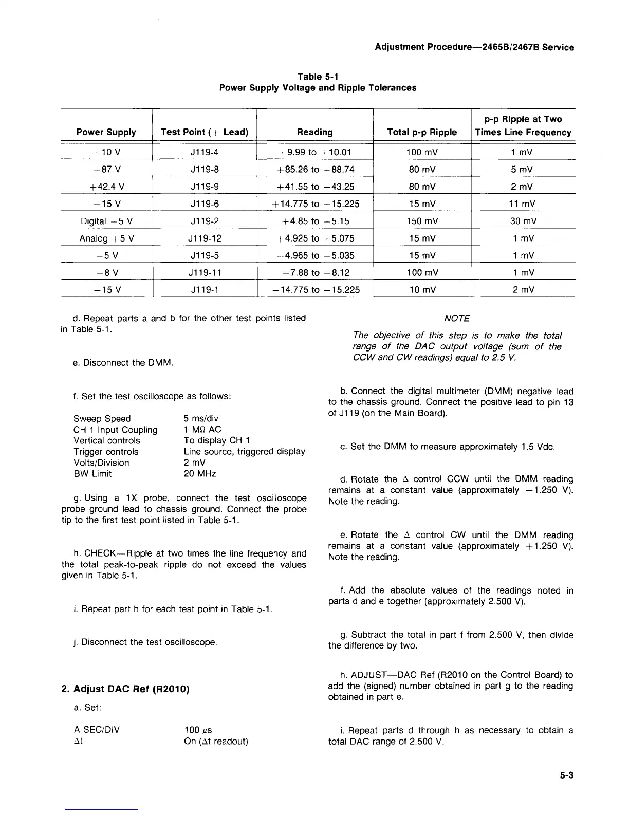
Table 5-1
Power Supply Voltage and Ripple Tolerances
Power Supply
+
10
V
+ 87 V
+ 42.4 V
+
15
V
Digital +5 V
Analog +5 V
-5 V
-8 V
-15 V
Test Point (+ Lead)
J119-4
J119-8
J119-9
J119-6
J119-2
J119-12
J119-5
J119-11
J119-1
Reading
+ 9.99 to +10.01
+ 85.26 to +88.74
+ 41.55 to +43.25
+ 14.775 to +15.225
+ 4.85 to +5.15
+4.925 to +5.075
-4.965 to -5.035
-7.88 to -8.12
-14.775 to -15.225
Total p-p Ripple
100 mV
80 mV
80 mV
15 mV
150 mV
15 mV
15 mV
100 mV
10 mV
p-p Ripple at Two
Times Line Frequency
1 mV
5mV
2mV
11 mV
30 mV
1 mV
1 mV
1 mV
2mV
d.
Repeat parts a and b for the other test points listed
in Table 5-1.
e. Disconnect the DMM.
NOTE
The objective of this step is to make the total
range of the DAC output voltage (sum of the
CCW and CW readings) equal to 2.5 V,
f. Set the test oscilloscope as follows:
Sweep Speed
CH 1 Input Coupling
Vertical controls
Trigger controls
Volts/Division
BW Limit
5 ms/div
1
MQ
AC
To display CH 1
Line source, triggered display
2 mV
20 MHz
g.
Using a 1X probe, connect the test oscilloscope
probe ground lead to chassis ground. Connect the probe
tip to the first test point listed in Table 5-1.
h. CHECK—Ripple at two times the line frequency and
the total peak-to-peak ripple do not exceed the values
given in Table 5-1.
i. Repeat part h for each test point in Table 5-1.
b. Connect the digital multimeter (DMM) negative lead
to the chassis ground. Connect the positive lead to pin 13
of J119 (on the Main Board).
c. Set the DMM to measure approximately 1.5 Vdc.
d.
Rotate the A control CCW until the DMM reading
remains at a constant value (approximately —1.250 V).
Note the reading.
e. Rotate the A control CW until the DMM reading
remains at a constant value (approximately +1.250 V).
Note the reading.
f. Add the absolute values of the readings noted in
parts d and e together (approximately 2.500 V).
j.
Disconnect the test oscilloscope.
g.
Subtract the total in part f from 2.500 V, then divide
the difference by two.
2.
Adjust DAC Ref (R2010)
a. Set:
h. ADJUST—-DAC Ref (R2010 on the Control Board) to
add the (signed) number obtained in part g to the reading
obtained in part e.
A SEC/DIV
At
100 MS
On (At readout)
i. Repeat parts d through h as necessary to obtain a
total DAC range of 2.500 V.
5-3