Adjustment Procedure—2465B/2467B Service
CAL 09—PARAMETRIC MEASUREMENTS
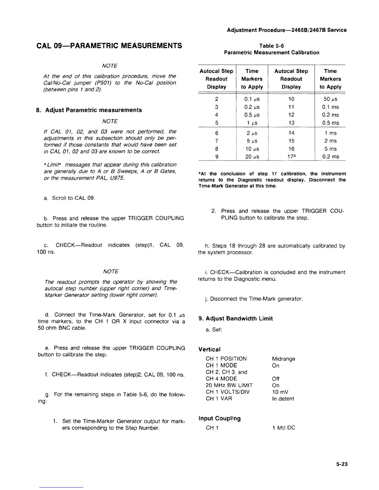
Table 5-6
Parametric Measurement Calibration
NOTE
At the end of this calibration procedure, move the
Cal/No-Cal jumper (P501) to the No-Cal position
(between pins 1 and 2).
8. Adjust Parametric measurements
NOTE
If CAL 01, 02, and 03 were not performed, the
adjustments in this subsection should only be
per-
formed if those constants that would have been set
in CAL 01, 02 and 03 are known to be correct.
" Limit" messages that appear during this calibration
are generally due to A or B Sweeps, A or B Gates,
or the measurement PAL, U975.
a. Scroll to CAL 09.
Autocal Step
Readout
Display
2
3
4
5
6
7
8
9
Time
Markers
to Apply
0.1 us
0.2 us
0.5 us
1 pS
2
MS
5 IUS
10 MS
20 MS
Autocal Step
Readout
Display
10
11
12
13
14
15
16
17
a
Time
Markers
to Apply
50 fis
0.1 ms
0.2 ms
0.5 ms
1 ms
2 ms
5 ms
0.2 ms
a
At the conclusion of step 17 calibration, the instrument
returns to the Diagnostic readout display. Disconnect the
Time-Mark Generator at this time.
b. Press and release the upper TRIGGER COUPLING
button to initiate the routine.
Press and release the upper TRIGGER
COU-
PLING button to calibrate the step.
c. CHECK—Readout indicates
(step)1,
CAL 09,
100 ns.
h. Steps 18 through 28 are automatically calibrated by
the system processor.
NOTE
The readout prompts the operator by showing the
autocal step number (upper right corner) and Time-
Marker Generator setting (lower right corner).
i. CHECK—Calibration is concluded and the instrument
returns to the Diagnostic menu.
Disconnect the Time-Mark generator.
d.
Connect the Time-Mark Generator, set for 0.1 ^s
time markers, to the CH 1 OR X input connector via a
50 ohm BNC cable.
9.
Adjust Bandwidth Limit
a. Set:
e. Press and release the upper TRIGGER COUPLING
button to calibrate the step.
f. CHECK—Readout indicates (step)2, CAL 09, 100 ns.
g.
For the remaining steps in Table 5-6, do the follow-
ing:
1.
Set the Time-Marker Generator output for mark-
ers corresponding to the Step Number.
Vertical
CH 1 POSITION
CH 1 MODE
CH 2, CH 3, and
CH 4 MODE
20 MHz BW LIMIT
CH 1 VOLTS/DIV
CH 1 VAR
Input Coupling
CH 1
Midrange
On
Off
On
10 mV
In detent
1 MQ DC
5-23