Maintenance—2465B/2467B Service
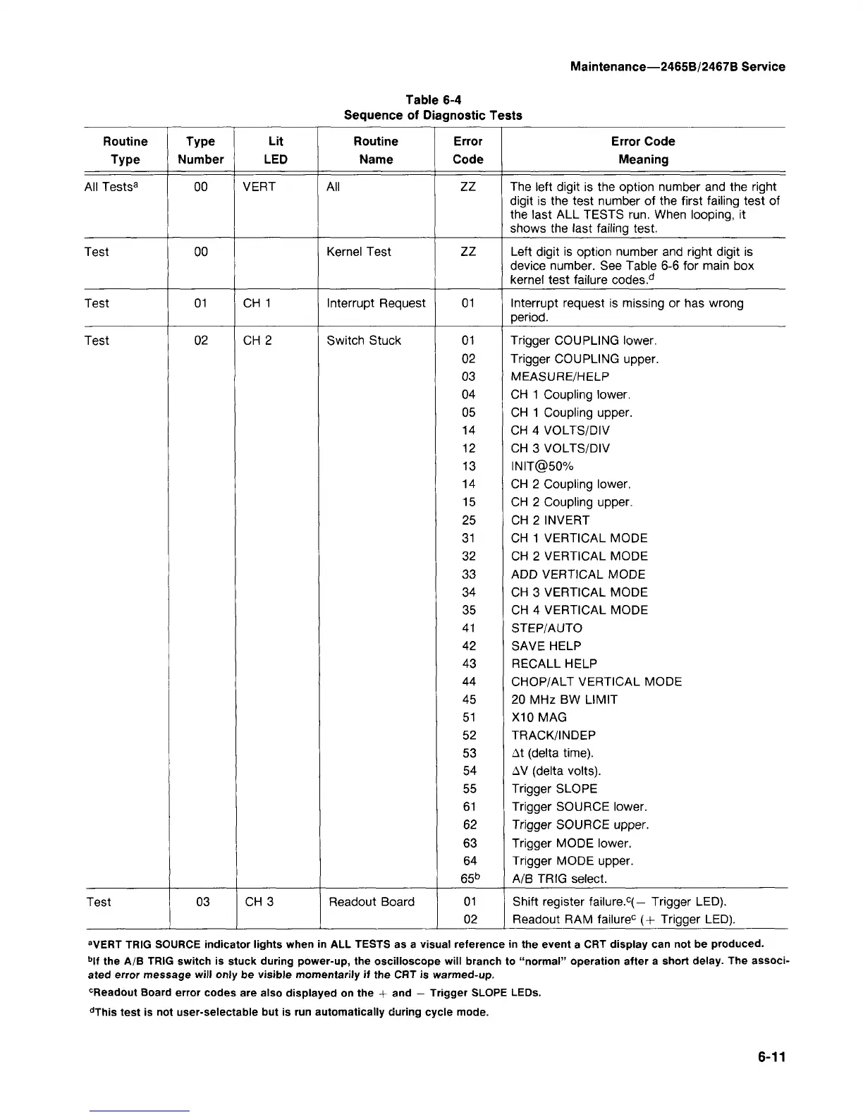
Table 6-4
Sequence of Diagnostic Tests
Routine Type
Type
All Tests
3
Test
Test
Test
Test
Number
00
00
01
02
03
Lit
LED
VERT
CH 1
CH 2
CH 3
Routine
Name
All
Kernel Test
Interrupt Request
Switch Stuck
Readout Board
Error
Code
zz
zz
01
01
02
03
04
05
14
12
13
14
15
25
31
32
33
34
35
41
42
43
44
45
51
52
53
54
55
61
62
63
64
65
b
01
02
Error Code
Meaning
The left digit is the option number and the right
digit is the test number of the first failing test of
the last ALL TESTS run. When looping, it
shows the last failing test.
Left digit is option number and right digit is
device number. See Table 6-6 for main box
kernel test failure codes.
d
Interrupt request is missing or has wrong
period.
Trigger COUPLING lower.
Trigger COUPLING upper.
MEASURE/HELP
CH 1 Coupling lower.
CH 1 Coupling upper.
CH 4 VOLTS/DIV
CH 3 VOLTS/DIV
INIT@50%
CH 2 Coupling lower.
CH 2 Coupling upper.
CH 2 INVERT
CH 1 VERTICAL MODE
CH 2 VERTICAL MODE
ADD VERTICAL MODE
CH 3 VERTICAL MODE
CH 4 VERTICAL MODE
STEP/AUTO
SAVE HELP
RECALL HELP
CHOP/ALT VERTICAL MODE
20 MHz BW LIMIT
X10MAG
TRACK/INDEP
At (delta time).
AV (delta volts).
Trigger SLOPE
Trigger SOURCE lower.
Trigger SOURCE upper.
Trigger MODE lower.
Trigger MODE upper.
A/B TRIG select.
Shift register failure.
c
(— Trigger LED).
Readout RAM failure
0
(+ Trigger LED).
a
VERT TRIG SOURCE indicator lights when in ALL TESTS as a visual reference in the event a CRT display can not be produced.
b
lf the A/B TRIG switch is stuck during power-up, the oscilloscope will branch to "normal" operation after a short delay. The associ-
ated error message will only be visible momentarily if the CRT is warmed-up.
c
Readout Board error codes are also displayed on the + and - Trigger SLOPE LEDs.
d
This test is not user-selectable but is run automatically during cycle mode.
6-11