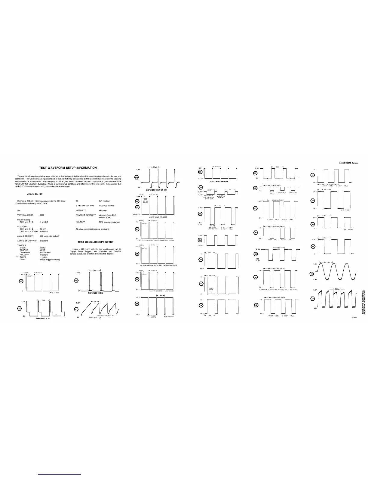
TEST WAVEFORM SETUP INFORMATION
The numbered waveforms below were obtained
at
the test points indicated on the accompanying schematic diagram and
board dolly. The waveforms are representative
of
signals that may be expected
at
the associated points when the following
setup conditions are observed. Any change(s) from the given setup conditions required
to
produce
a
given waveform are
noted with that waveform illustration. Where
B
Sweep setup conditions are referenced with
a
waveform,
it is
assumed that
the
B
SEC/DIV knob is set
to
100 ^s/div unless otherwise noted.
2467B SETUP
—«-|
1.09MS
|—
Connect
a
200-mV, 1-kHz squarewave to the CH1 input
of the oscilloscope using
a
BNC cable.
Set:
VERTICAL MODE
Input Coupling
CH 1 and CH
2
VOLTS/DIV
CH 1 and CH
2
CH
1
and CH 2 VAR
A and
B
SEC/DIV
A and
B
SEC/DIV VAR
TRIGGER
MODE
SOURCE
COUPLING
HOLDOFF
♦ SLOPE
LEVEL
CH1
1 Mfi DC
50 mV
In detent
200
MS
(knobs locked)
In detent
AUTO
VERT
NOISE REG
In detent
+ (plus)
Stably triggered display
AX
A REF OR DLY POS
INTENSITY
DLY readout
1000.0
MS
readout
Midrange
READOUT INTENSITY Minimum (once DLY
readout
is
set)
HOLDOFF
CCW (counterclockwise)
All other control settings are irrelevant.
TEST OSCILLOSCOPE SETUP
Using
a
X10 probe with
the
test oscilloscope,
set its
Trigger Slope, Trigger Level, Volts/Div
and
Time/Div
ranges as required to obtain the indicated displays.
4.BV
0
ov
-H
+ 5V
r\
EXPANDED VIEW OF 20A
(^-2.4ms~H
0
0
200
mV
-
BLANK
TIME
SET
BY
HOLDOFF
+SV
— p,
\
0
AUTO W/NO TRIGGER
U-2.4ms-»J
0V
A
AND
B
SEC/0IV KNOBS LOCKED (200us)W/NO TRIGGER
-HKA
+5V
—
k \
0
100
MS
B SWEEP SELECTED - W/NO TRIGGER
0
K-y
r
HOLDOFF
•-2.4KI8-*)
7.2V
0
ov
W/NO TRIGGER
3ms-
EXPANDED IN 21
4.8V
^
0V
<
7.2V
0
0V
-3n>9-
EXPANDEDIN 21A
EXPANDED
VIEWOF
20
A SEC/DIV
1
MS
-f\ n
\-m-2.4ttis-»\
HOLDOFF
+5V-
0
XI0
MAG SELECTED
-
W/NO TRIGGER
|«-2.4ms-»|
-H
H- READOUT
ACTIVE
W/NO
TRIGGER
2465B/2467B Service
0V
-1V-
0
0.2V-
-1.1V-
*
*
AUTO W/NO TRIGGER
:"L_n__n__ji
TRIGGERED
ON
U.
SWEEP-J
0SITIVE-G0INC "RUNNING
'
POS
SQUARE WAVE
0
0V
—
-0.2V
—
VARIES
W/
A
SWEEP
-
200JJS
A
REF
SETTING
B
SWEEP
-
100ps
0
-0.2V-
0
+5V
—
0
0V
—
•4
3ms »■
TRIG'D
SWEEP
(
0
^^^
f
-
3ms
-
2.5V
0
OV
-3ms-
0
-
3ms
H
HOLDOFF
+4V
—
+3V
—
L^
TRIG'D
SWEEP
ONLY
B
TRIGGERED
- Sins
H
HOLDOFF
|SWEEP|
0
+3V-
A SWEEP -
200MS
B SWEEP
100MS
-
3ms
H
HOLDOFF
|SWEEP|
0
A SWEEP
-
200MS
B
SWEEP
-
100ps
+2.2V
0
GND
-.5V
-3ms-
-
3ms
H
HOLDOFF
|SWEEP|
+5v—
r-
0
SWEEP ONLY, TRIGGERED AFTER
0ps
DELAY
ON
-SLOPE
-
3ms
H
HOLDOFF |SWEEP|
0
0V
A
SWEEP
-
200^s
B
SWEEP
-
100[JS
0
0V
■
-
3ms
H
HOLDOFF
ISWEEPl
A
SWEEP
-
200|js
B
SWEEP
-
100MS
[a
0.4ms-
0
W/NO TRIGGER
0.4ms
—
0
W/NO TRIGGER
- 0.4ms
-
0
+ .4V
4.5V
A
0
A
GNO
HAM
200ns
m
*
VH
A
i
HP
H
o
to
m
m
■o
to
>
<
m
■n
O
3D
s
w
6019-16