Maintenance—46SB Service
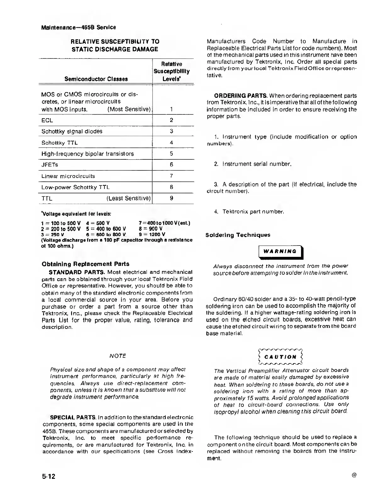
RELATIVE SUSCEPTIBILITY TO
STATIC DISCHARGE
DAMAGE
Semiconductor Classes
Relative
Susceptibility
Levels'
MOS or
CMOS
microcircuits
or dis-
cretes, or linear microcircuits
with MOS inputs.
(Most Sensitive) 1
ECL
2
Schottky
signal diodes 3
Schottky TTL
4
High-frequency
bipolar transistors 5
JFETs
6
Linear microcircuits
7
Low-power Schottky
TTL 8
TTL
(Least
Sensitive) 9
Voltage
equivalent for levels:
1
=
100 to 500 V 4
=
500 V 7
=
400to 1000
V(est.)
2
=
200 to 500 V 5
=
400 to 600 V 8
=
900 V
3
=
250 V 6
=
600 to 800 V 9
=
1200 V
(Voltage discharge from a 100 pF
capacitor through a resistance
of 100 ohms.)
Obtaining Replacement
Parts
STANDARD PARTS. Most electrical and
mechanical
parts can be
obtained through your local Tektronix
Field
Office or
representative. However, you should be able to
obtain
many
of
the standard electronic components
from
a
local commercial source in your
area. Before you
purchase or order a part
from
a
source other than
Tektronix, Inc., please
check the Replaceable Electrical
Parts List
for
the proper value, rating, tolerance
and
description.
NOTE
Physical size and shape
of
a
component may affect
instrument performance,
particularly at high fre-
quencies. Always use
direct-replacement com-
ponents, unless it is known that a
substitute will not
degrade instrument performance.
SPECIAL PARTS. I n addition to the
standard electronic
components, some
special components are used
in
the
465B.
These components are
manufactured or selected by
Tektronix, Inc. to meet specific
performance re-
quirements, or are
manufactured for Tektronix, Inc. in
accordance with our specifications (see
Cross Index-
Manufacturers Code Number to
Manufacture
in
Replaceable Electrical Parts List for code numbers). Most
of the
mechanical
parts used in this instrument have been
manufactured by Tektronix, Inc. Order all special parts
directly from
your
local Tektronix Field Office or represen-
tative.
ORDERING PARTS. When ordering replacement parts
from Tektronix, Inc., it
is
imperativethat all of the following
information be included in order to ensure receiving the
proper parts.
1.
Instrument
type
(include modification
or
option
numbers).
2.
Instrument serial number.
3.
A description of the part (if electrical, include the
circuit number).
4.
Tektronix part number.
Soldering Techniques
Always
disconnect the
instrument from the power
source
before attempting to
solder in the instrument.
Ordinary 60/40 solder
and
a
35-
to 40-watt
pencil-type
soldering iron can be used to
accomplish the
majority of
the soldering. If a higher
wattage-rating
soldering iron is
used on the
etched circuit boards,
excessive heat can
cause the etched
circuit wiring to
separate from the board
base
material.
The
Vertical
Preamplifier
Attenuator circuit
boards
are made
of
material easily
damaged
by
excessive
heat. When
soldering to these
boards, do not
use
a
soldering
iron with a
rating of more
than ap-
proximately 15
watts. Avoid
prolonged
applications
Of heat to
circuit-board
connections.
Use only
isopropyl
alcohol when
cleaning this circuit
board.
The
following technique should be used to
replace a
component on the circuit board.
Most components can be
replaced without
removing the boards from the
instru-
ment.
@
5-12