Operating Instructions—465B Service
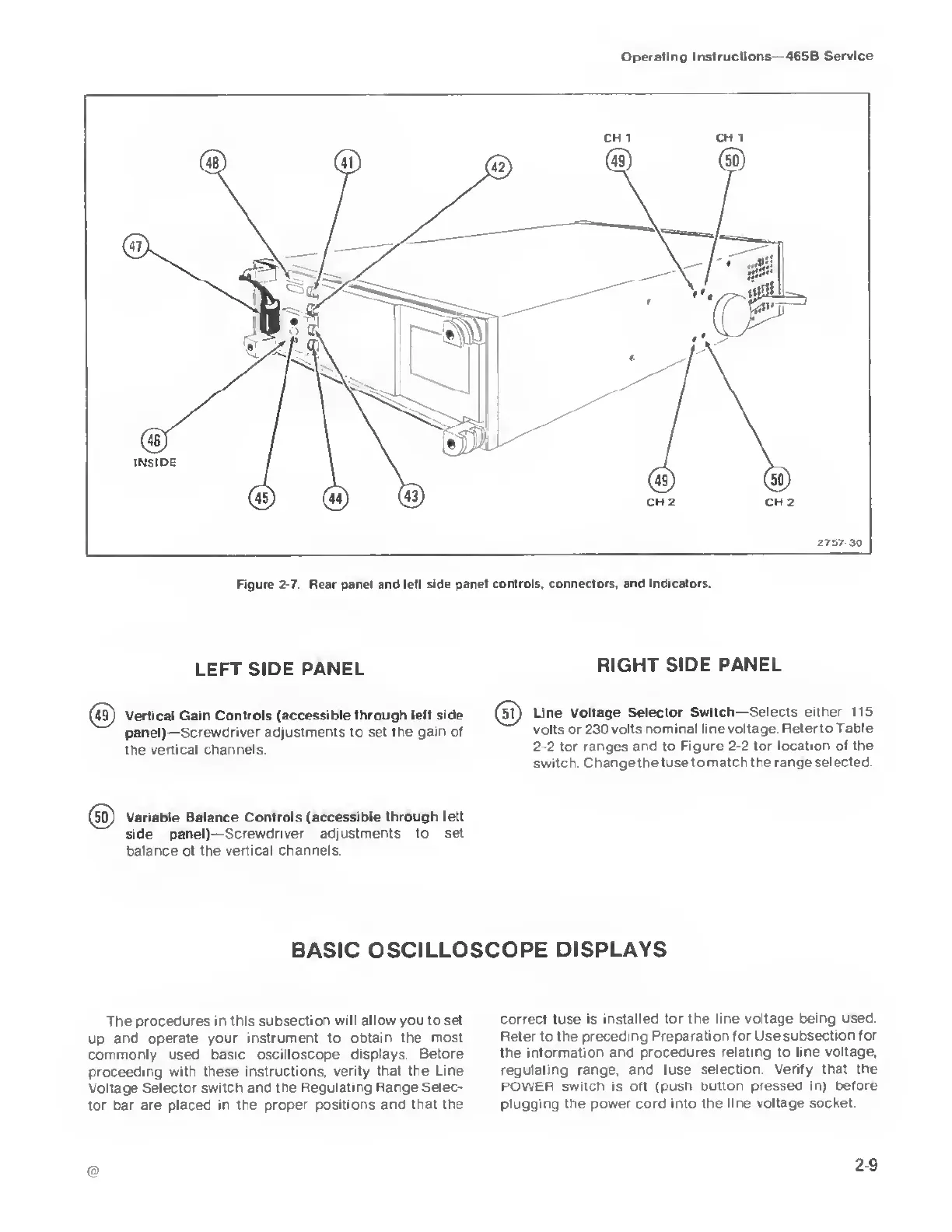
Figure
2-7
Rear panel and left side
panel controls, connectors, and indicators.
LEFT SIDE
PANEL
RIGHT SIDE
PANEL
(49)
Vertical Gain Controls
(accessible through left side
panel)—Screwdriver adjustments to
set
the
gain of
the vertical
channels.
(5u
Line Voltage
Selector Switch—
Selects either 115
volts
or
230 volts
nominal
line
voltage Refer to
Table
2-2
for ranges and to
Figure
2-2
for location of the
switch Changethe fuse to
match the range selected.
Variable Balance
Controls (accessible through
left
side panel)—
Screwdriver adjustments to set
balance of the
vertical channels.
BASIC
OSCILLOSCOPE DISPLAYS
The procedures
in this subsection will allow you to
set
up and operate your
instrument
to
obtain the
most
commonly used
basic oscilloscope displays Before
proceeding with
these instructions,
verify that the Line
Voltage
Selector switch and the Regulating
Range Selec-
tor bar are
placed in the proper positions and
that the
correct fuse is installed for the
line voltage being used.
Refer
to
the preceding
Preparation for
Use
subsection for
the information and procedures
relating to line voltage,
regulating range, and fuse
selection Verify that the
POWER switch is off (push button
pressed in) before
plugging the
power cord into the line voltage
socket.
@
29