Theory of Operation—465B
Service
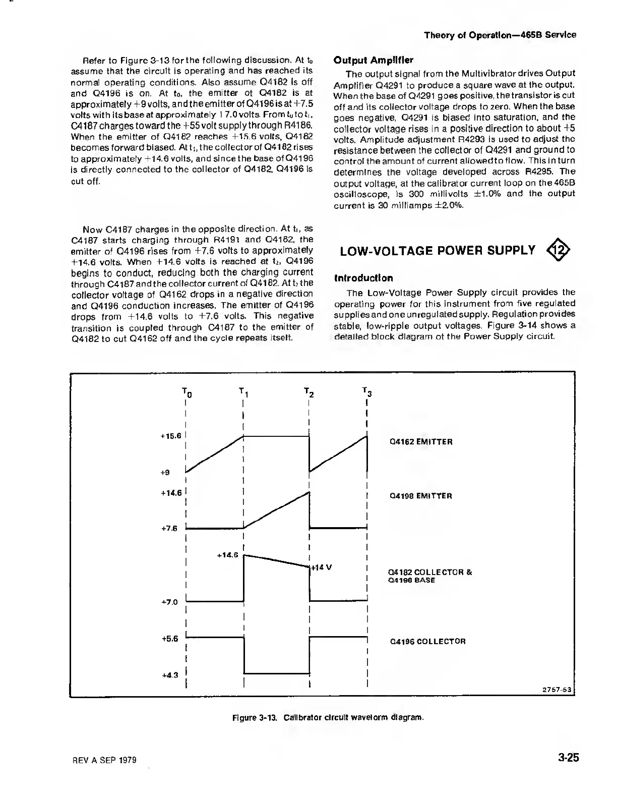
Refer to
Figure
3-13
for the
following discussion. At
to
assume
that the circuit is operating
and has reached its
normal operating
conditions. Also assume
Q4182
is off
and Q4196 is
on. At t
0,
the emitter of
Q4182 is at
approximately +9 volts,
and
the
emitter
of
Q4196is at +7.5
volts with its base at
approximately + 7.0 volts. From
to
tot,,
C41 87
charges toward the +55
volt supply through R4186.
When the
emitter
of
04182 reaches
+15.6
volts,
Q4182
becomes forward biased.
At
ti,
the collector of Q41 82 rises
to
approximately +14.6 volts,
and since the base of Q4196
is directly
connected to the collector of Q4182,
Q4196 is
cut off.
Now C4187
charges in the
opposite direction.
At
ti,
as
C4187
starts
charging
through R4191
and Q4182, the
emitter of
Q4196 rises
from +7.6 volts to
approximately
+14.6 volts.
When +14.6 volts is
reached at t
2 ,
Q4196
begins to
conduct,
reducing both the
charging current
through C4187
and the
col lector current of
04182. At
t?
the
collector
voltage of
Q4162 drops
in
a
negative
direction
and
Q4196 conduction
increases.
The emitter of Q4196
drops from
+14.6 volts to
+7.6 volts.
This negative
transition
is
coupled through C4187
to the
emitter
of
Q4182 to cut
Q4162 off and the
cycle repeats
itself.
Output
Amplifier
The
output signal from
the Multivibrator drives
Output
Amplifier Q4291 to
produce
a
square wave at
the output.
When the base
of
Q4291
goes
positive, thetransistor is
cut
off
and its collector voltage
drops
to
zero. When the base
goes
negative, Q4291 is
biased into saturation,
and the
collector
voltage rises in a positive
direction to about
+5
volts.
Amplitude adjustment R4293
is used to adjust
the
resistance between the collector of
Q4291 and
ground to
control the
amount
of
current allowed to flow.
This
in
turn
determines the voltage
developed across R4295.
The
output voltage, at
the calibrator
current loop on the465B
oscilloscope, is 300
millivolts ±1.0% and the
output
current is 30
milliamps ±2.0%.
LOW-VOLTAGE
POWER
SUPPLY
^
Introduction
The Low-Voltage Power
Supply circuit
provides the
operating power for this
instrument from five
regulated
supplies and one
unregulated supply.
Regulation provides
stable,
low-ripple output voltages.
Figure
3-14
shows a
detailed block
diagram
of the
Power Supply circuit.
REV
A SEP
1979
3-25