Operating Instructions—465B Service
MOUNTING PROCEDURE
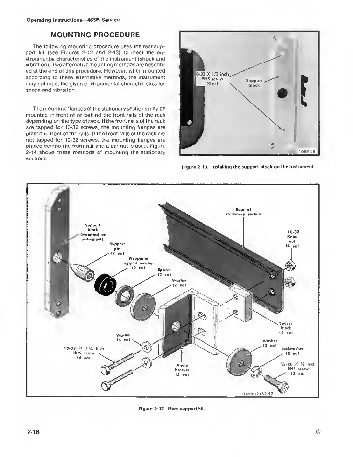
The following mounting procedure uses the rear sup-
port kit (see Figures
2-12
and 2-13) to meet the en-
vironmental characteristics of the instrument (shock and
vibration). Two alternative mounting methods are describ-
ed at
the
end of
this
procedure
However, when mounted
according to these alternative methods, the
instrument
may not meet the given
environmental
characteristics for
shock and vibration.
The mounting flanges
of
the stationary sections may be
mounted in front of
or
behind the front rails of the rack
depending on the type of rack. If the front rails of the rack
are tapped for
10-32
screws, the mounting flanges are
placed in front of the rails. If the front rails of the rack are
not tapped for
10-32
screws, the mounting flanges are
placed benina the front rail ana a oar nut is usea. Figure
2-14
shows these methods of mounting the stationary
sections.
Figure
2-13.
Installing the support block on the
instrument.
Washer
14 eal
10-32
X
1V4
inch
HHS screw
14
eal
on
instrument!
Rear
of
section
10-32
Keps
nut
Spacer
block
12 eal
Washer
12
eal
Lockwasher
(2
eal
-20
X
%
inch
HHS screw
Figure 2-12.
Rear support kit.
2-16