Operating
Instructions—
465B Service
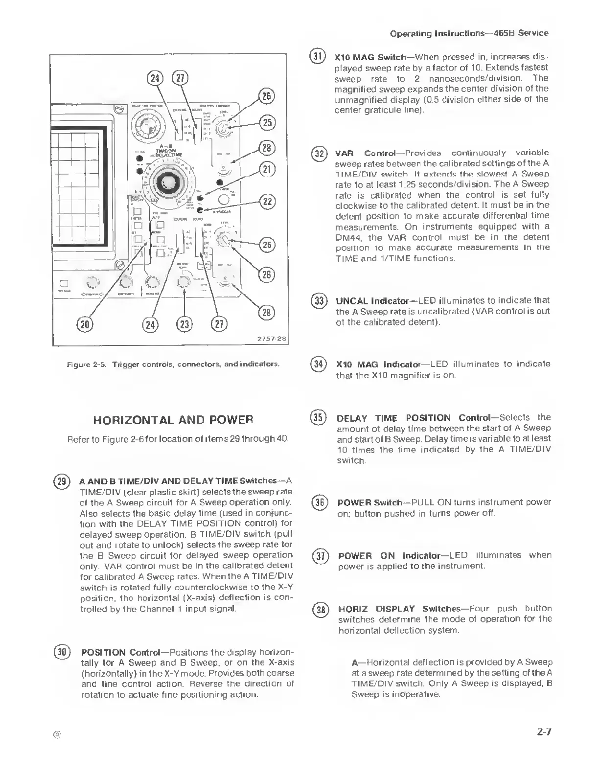
Figure
2-5. Trigger controls, connectors, and
indicators.
1)
X10
MAG Switch—
When pressed in, increases
dis-
played
sweep rate
by
a
factor of 10 Extends
fastest
sweep
rate to 2
nanoseconds/division.
The
magnified sweep expands
the center
division of the
unmagnified display
(0.5 division
either side of the
center
graticule line).
32)
VAR Control Provides
continuously
variable
sweep rates
between the calibrated
settings
of the A
TIME/DIV
switch It extends the slowest A Sweep
rate
to at
least 1.25
seconds/division. The A Sweep
rate
is
calibrated when
the control is set
fully
clockwise to the
calibrated detent. It
must
be
in the
detent
position
to
make accurate
differential
time
measurements.
On instruments
equipped with a
DM44. the
VAR control must be
in the detent
position to
make accurate
measurements in the
TIME and 1/TIME
functions.
UNCAL
Indicator— LED illuminates to indicate
that
the
A
Sweep
rate is uncalibrated
(VAR
control is
out
of
the calibrated detent)
(34)
X10
MAG Indicator— LED
illuminates to indicate
that the X10
magnifier is on.
HORIZONTAL AND
POWER
Refer to Figure
2-6
for location of
items
29
through 40
(35)
DELAY TIME
POSITION
Control—Selects the
amount of delay
time between the
start of A Sweep
and start of B Sweep.
Delay time is
variable to at least
10 times
the time indicated by the A
TIME/DIV
switch.
(29)
A
AND B TIME/DIV
AND DELAY TIME
Switches—
A
TIME/DIV
(clear plastic skirt)
selects the sweep rate
of the A Sweep
circuit for A Sweep
operation only
Also selects the
basic delay time
(used in conjunc-
tion with the
DELAY TIME
POSITION control) for
delayed sweep
operation B
TIME/DIV switch
(pull
out and rotate to
unlock) selects
the sweep rate for
the B Sweep
circuit for delayed
sweep
operation
only. VAR
control must be in
the calibrated
detent
for calibrated
A Sweep rates.
When the A
TIME/DIV
switch is rotated fully
counterclockwise to the X-Y
position, the
horizontal (X-axis)
deflection is con-
trolled
by
the Channel 1
input signal
(30)
POSITION Control—Positions the display
horizon-
tally
for A
Sweep and B Sweep, or on
the X-axis
(horizontally) in the X-Y mode. Provides both
coarse
and fine control action. Reverse the
direction of
rotation to actuate
fine positioning action
POWER
Switch— PULL
ON turns instrument
power
on; button
pushed in turns
power off.
(37)
POWER ON
Indicator—LED
illuminates when
power is applied to
the
instrument.
(3fi)
HORIZ
DISPLAY Switches— Four push
button
switches determine the
mode of
operation for the
horizontal deflection
system.
A—
Horizontal deflection is provided by A Sweep
at a sweep
rate determined by the setting of the
A
TIME/DIV switch. Only A Sweep is
displayed, B
Sweep is
inoperative.