Operating Instructions—465B Service
A INTEN—
Displays the A Sweep
at
a rate
deter-
mined
by
the
A
TIME/DIV switch. An intensified
portion
can appear on the
display
during the B
Sweep time. This switch position provides an
indication of both the duration and position of the
B
Sweep
(delayed
sweep)
witn
respect to tne
a
S
weep (delaying sweep)
ALT—
Alternates
the displays between the A
INTEN and B DLY'D Sweeps. In ALT operation,
use
TRACE SEP
to
vertically position
B
Trace;
use B INTENSITY
control
to adjust B Trace
intensity.
B DLY'D—Displays
only the B Sweep The B
Sweep rate is determined
by
the
B
TIME/DIV
switch, with
the
delay
time determined by the
setting
of both the A
TIME/DIV
switch and the
DELAY TIME POSITION control.
njn TRACE SEP Control
—
Positions the
B
Sweep
ver-
W
tically when the ALT HORIZ DISPLAY
mode
is
selected
®
B INTENSITY
Control—Determines the intensity of
the B
Trace
(interacts with INTENSITY control)
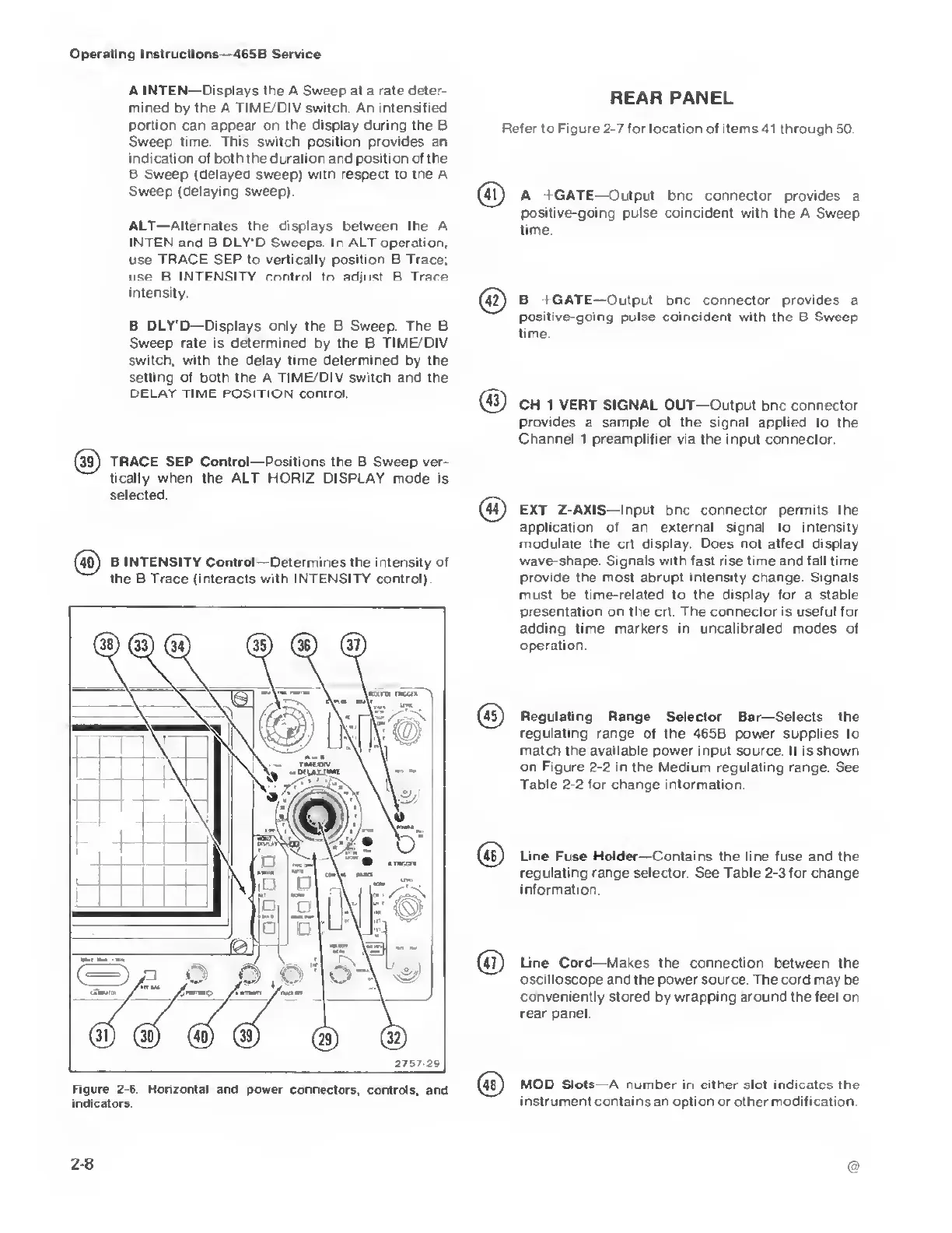
Figure
2-6.
Horizontal and
power connectors, controls,
and
indicators.
REAR PANEL
Refer
to
Figure
2-7
for
location of items
41 through 50.
(4l) A +GATE—Output bnc connector provides a
positive-going pulse coincident with
the A Sweep
time.
(
42
)
B
1
GATE—Output bnc connector provides a
positive-going pulse coincident with the B Sweep
time
®
CH 1 VERT SIGNAL OUT—
Output bnc connector
provides
a sample of the signal applied to the
Channel
1
preamplifier
via the input connector
(44)
EXT Z-AXIS—Input bnc connector permits the
application of an external signal to intensity
modulate the crt display Does not affect display
wave-shape Signals with fast rise time and fall time
provide the most abrupt intensity change. Signals
must
be
time-related to the display for a stable
presentation on the crt The connector is useful for
adding time markers in uncalibrated modes of
operation.
Regulating Range
Selector Bar
—
Selects the
regulating
range
of the 465B power supplies to
match
the available
power input source. It is shown
on Figure 2-2
in the Medium regulating range See
Table
2-2
for change information.
Line Fuse Holder—Contains the line fuse and the
regulating range selector See Table
2-3
for change
information.
(
4
?)
Line Cord—Makes the connection between the
oscilloscope and the power source. The cord may
be
conveniently stored
by
wrapping around the
feet on
rear panel
48)
MOD Slots A number in either slot
indicates the
instrument contains an option
or other
modification
2-8