Options—465B
Service
Option 05
THEORY
OF
OPERATION
Introduction
This
section
describes circuitry
unique
to Option 05.
Refer
to the Theory
of Operation section
of this manual for
information
concerning those
portions of the
oscilloscope
circuitry that
are unchanged
by Option
05.
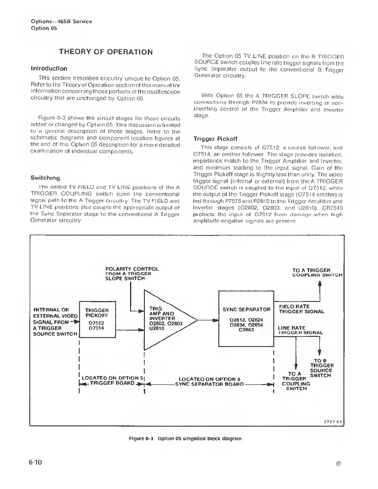
Figure 6-3
shows the
circuit stages for
those circuits
added or changed
by Option
05 This discussion
is
limited
tu
a
general
description
of those stages.
Refer to the
schematic diagrams
and component
location
figures at
the end
of this Option
05 description
for a more detailed
examination
of individual
components.
Switching
The added
TV
FIELD
and TV LINE positions
of the A
TRIGGER
COUPLING switch
open the conventional
signal path
to the A Trigger
circuitry The
TV FIELD and
TV LINE
positions also
couple the appropriate output
of
the Sync
Separator stage
to the conventional
A Trigger
Generator circuitry
The Option
05
TV LINE
position
on the B TRIGGER
SOURCE
switch
couples line
rate trigger
signals from
the
Sync
Separator
output to the
conventional
B Trigger
Generator circuitry.
With Option
05 the
A TRIGGER
SLOPE
switch
adds
connections
through P2834
to provide
inverting
or non-
inverting
control of the
Trigger Amplifier
and
Inverter
stage.
Trigger Pickoff
This
stage consists of
Q7512,
a
source
follower,
and
Q7514, an emitter follower. The stage provides
isolation,
impedance
match to the Trigger Amplifier and
Inverter,
and minimum
loading to the input signal.
Gain of the
Trigger Pickoff stage is slightly less
than unity. The video
trigger signal (internal
or external) from the A TRIGGER
SOURCE switch is coupled to
the input of Q7012, while
the output of the Trigger Pickoff
stage (07514 emitter) is
fed through P7575 and
P2810 to the Trigger Amplifier and
Inverter stages
(02802, Q2803. and U2810) CR7510
protects
the input of 07512
from
damage when high
amplitude negative
signals are present.
Figure
6-3.
Option
05
simplified block diagram

 Loading...


