Introduction and
Specification—465B Service
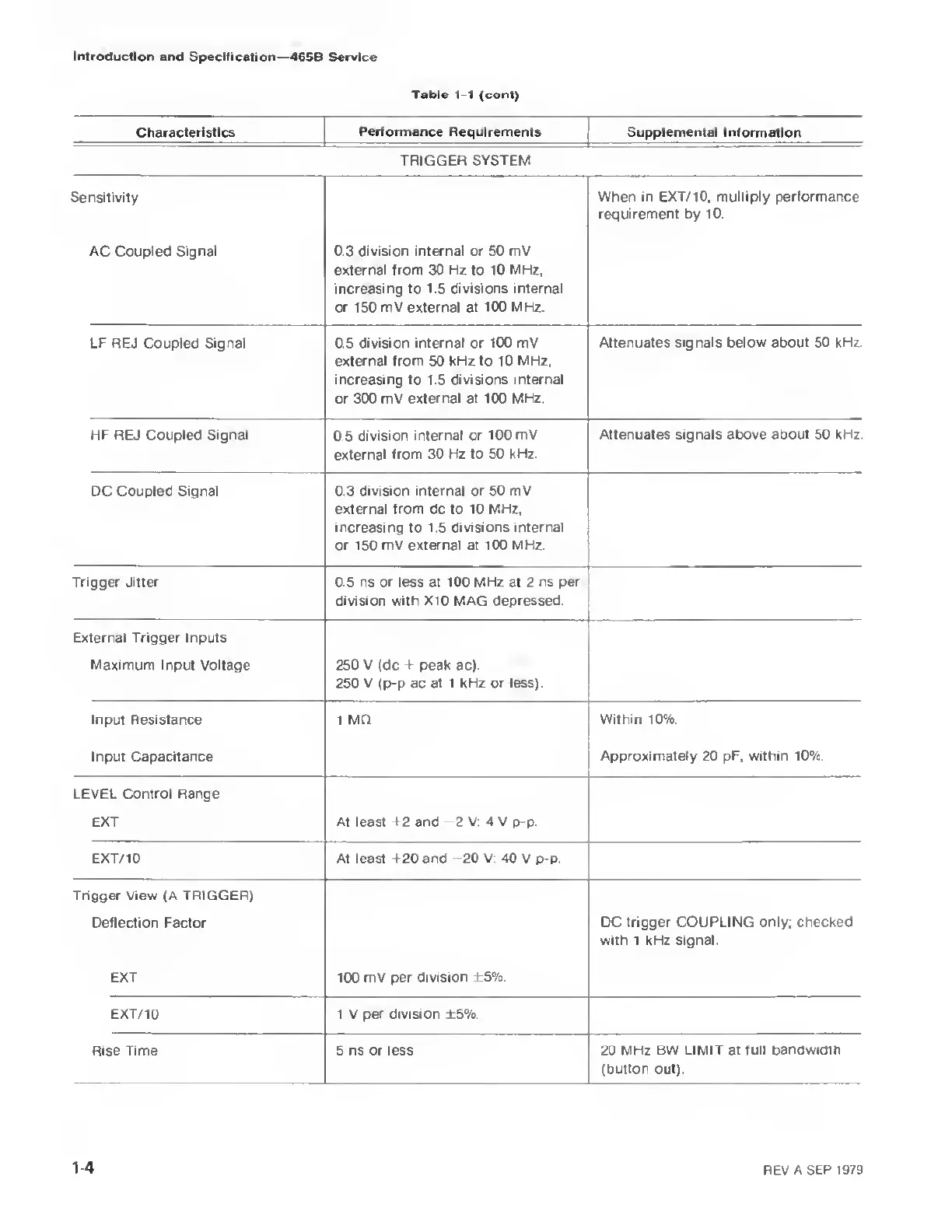
Table 1-1 (cont)
Characteristics
Performance
Requirements Supplemental
Information
TRIGGER SYSTEM
Sensitivity When in EXT/10,
multiply performance
requirement by 10.
AC Coupled Signal 0.3 division
internal or
50
mV
external from 30 Hz to 10
MHz,
increasing to 1.5 divisions internal
or 150 mV external at 100 MHz.
LF REJ Coupled Signal 0.5 division internal or 100 mV
external from 50 kHz to 10
MHz.
increasing to 1.5 divisions
internal
or 300 mV external at 100 MHz.
Attenuates signals below about 50 kHz.
HF REJ Coupled Signal
0 5
division
internal or 100 mV
external from 30
Hz to 50 kHz.
Attenuates signals above about 50 kHz.
DC Coupled Signal 0.3 division internal or 50
mV
external from
dc
to 10 MHz,
increasing to 1.5 divisions
internal
or 150 mV external at 100
MHz.
Trigger Jitter 0.5 ns or less at 100 MHz at 2
ns per
division with X10 MAG depressed.
f
External Trigger Inputs
Maximum Input Voltage 250 V (dc -t peak ac).
250 V
(p-p
ac at 1 kHz or less).
Input Resistance 1 MO
Within 10%.
Input Capacitance
Approximately
20
pF, within 10%.
LEVEL Control Range
EXT At least +2 and
-2
V; 4 V p-p.
EXT/ 10 At least f 20 and
-20
V; 40 V p-p.
Trigger View
(A
TRIGGER)
Deflection Factor DC
trigger COUPLING only; checked
with 1 kHz
signal.
EXT 100 mV
per division ±5%.
EXT/10 1 V
per division ±5%.
Rise Time 5 ns or less
20 MHz BW LIMIT at full
bandwidth
(button out).
1-4
REV A SEP
1979