Options—
465B Service
Option 07
Turn-Off Circuit
Q1622 is off under normal operating conditions until
the du suurue drups below 22 volts arid causes Q1622 to
conduct. Q1622 does not conduct during
12-volt dc
operation, since the Turn-off Level circuit is disabled.
CR1625, CR1626, CR1627. and CR1628 form a bridge
rectifier. The
inverter
waveform is rectified to provide
operating power for the Turn-off circuit. The inverter
spikes are filtered
by C1626 to
keep them from firing
Q1626
(silicon-controlled
rectifier).
Resistor R1623
prevents
C1626
from
charging
to the peak-to-peak
level
of
the inverter spikes
When
Q1622 is
turned
on,
it saturates. The high current
path required for feedback current via CR1625 or CR1626
is
provided
by C1622.
Whenever the inverter is shut down,
Cl 622 discharges through R1622.
If 24 volts
dc
is accidentally applied when the mode
switch is in the 12-volt position, transformer T14500
attempts to produce two times the correct feedback This
is sufficient to cause VR1622 to conduct VR1622 provides
the firing current for silicon-controlled rectifier
Q
1626. Scr
Q1626 fires and shorts out the bridge rectifier and the
primary of
T1631, stopping the
inverter. R1625 prevents
Q1626 from
being fired by
inverter noise
R1624
and
C1626
provide holding
current for Q1626.
keeping
it
conducting
until the surge created by the
over-voltage
conditions have terminated.
Diode CR1624 permits rapid
charging
of C1626.
Start Circuit
When SI 601 is closed,
the external dc source is
applied
to
C1614,
VR1641. and R1645. The
initial surge
is
coupled
to Q1642
through
C1614,
VR1639, and
R1641. Transistor
Q1642 sat urates
until
C1614
charges
through R1639tothe
value determined by
VR1639 and the
base-emitter junc-
tion of Q1642
(about 5.7
volts), then QI642 is cut off.
R1641
limits the base
current in Q1642. Zener diode
VR1639, once C1614 is
charged, makes Q1642
insensitive
to input variations. R1642
limits Q1642
collector current.
Q1644, R1645,
and VR1641
provide
a
constant current
during
the time Q1642 is
saturated, regardless of the dc
source voltage CR1643 is
reverse biased by this
starting
current. The
starting current is
applied
to the
inverter
transistors
through
T1631.
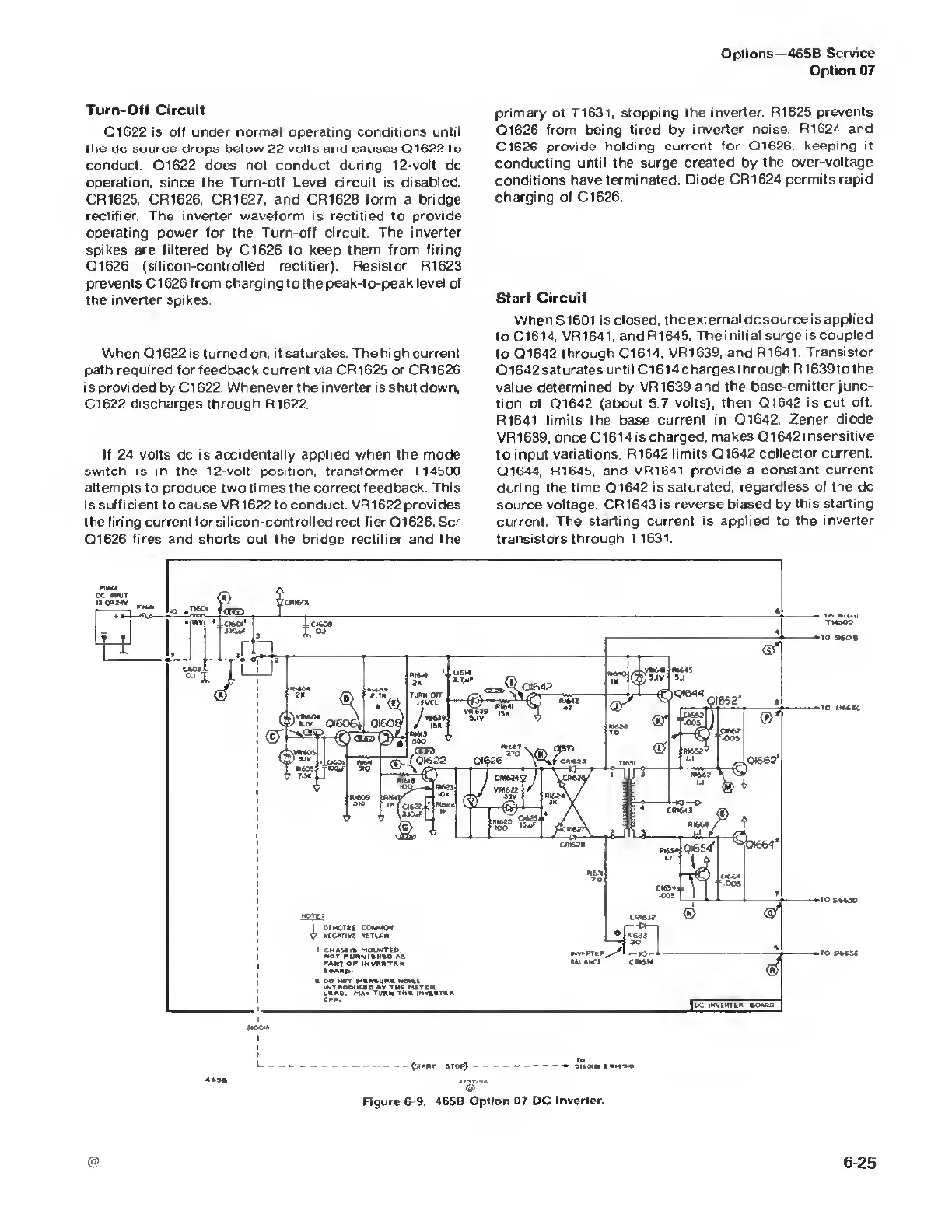
Figure
6-9. 465B Option 07 DC
Inverter.
 Loading...


