Options—
465B Service
Option 07
Circuit Board Chassis Removal
The Option 07 circuit board is mounted on a small
chassis located between
the
power transformer and the
crt shield
To remove the
chassis,
first
remove the two
thread-forming
screws
located
at
the top
of the chassis.
Then remove one screw at the bottom right side of the
chassis, just below the power transformer
ADJUSTMENT
Option 07 may be calibrated without removing it from
the oscilloscope
In the following
procedures the reference
letters
(A),
(B), etc
,
refer
to points indicated on the schematic
diagram
(Figure
6-9)
and circuit board illustrations
NOTE
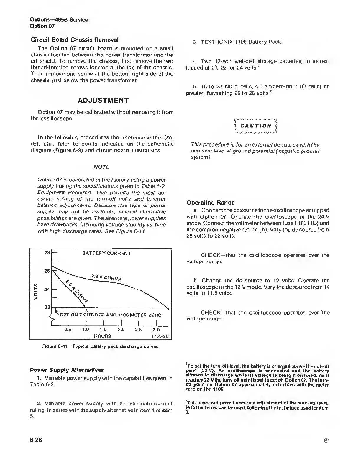
Option 07 is calibiated at the factory using
a
power
supply having
the specifications given in Table
6-2,
Equipment Required. This
permits the most ac-
curate setting
of
the turn-off
volts and inverter
balance
adjustments. Because this type
of power
supply
may
not be available, several alternative
possibilities
are given. The alternate
power supplies
have drawbacks,
including voltage stability
vs.
time
with
high discharge rates.
See
Figure
6-
1
1.
3. TEKTRONIX 1106 Battery Pack
1
4 Two 12-volt wet-cell storage batteries, in series,
tapped at
20, 22.
or 24 volts.
2
5.
18
to 23
NiCd cells, 4.0 ampere-hour (D cells) or
greater, furnishing
20 to
28 volts.
2
This
procedure is tor
an external
dc
source
with the
negative lead
at ground potential
(negative ground
system).
Operating Range
a. Connect the dc source to the oscilloscope equipped
with Option 07 Operate the oscilloscope in the 24 V
mode.
Connect
the
voltmeter between fuse
F1601 (B)
and
the common negative return (A). Vary the dc source from
28 volts to 22 volts
Figure 6-11.
Typical battery pack discharge
curves.
CHECK—that the oscilloscope operates over the
voltage range
b
Change
the dc
source to 12 volts Operate the
oscilloscope in the
12 V
mode.
Vary
the
dc
source from 14
volts to 115 volts.
CHECK—that the oscilloscope operates
over
fhe
voltage range
Power Supply Alternatives
1 Variable power supply
with the capabilities given in
Table
6-2.
2. Variable
power supply with an
adequate
current
rating,
in
series
with the supply alternative
in item 4 or
item
5
To set the
turn-off level, the battery is
charged above the cut-otf
point (22 V). An oscilloscope
is
connected
and the battery
allowed to discharge
while its voltage is being
monitored. As it
reaches
22 V the turn-oil point is set to cut otf Option
07. The turn-
off point
on
Option
07 approximately coincides with
the meter
zero on the 1106.
This does not
permit accurate adjustment
of
the
turn-ofl
level.
NiCd batteries can
be used, following the technique
used
lor
item
 Loading...


