Operating Instructions—
465B Service
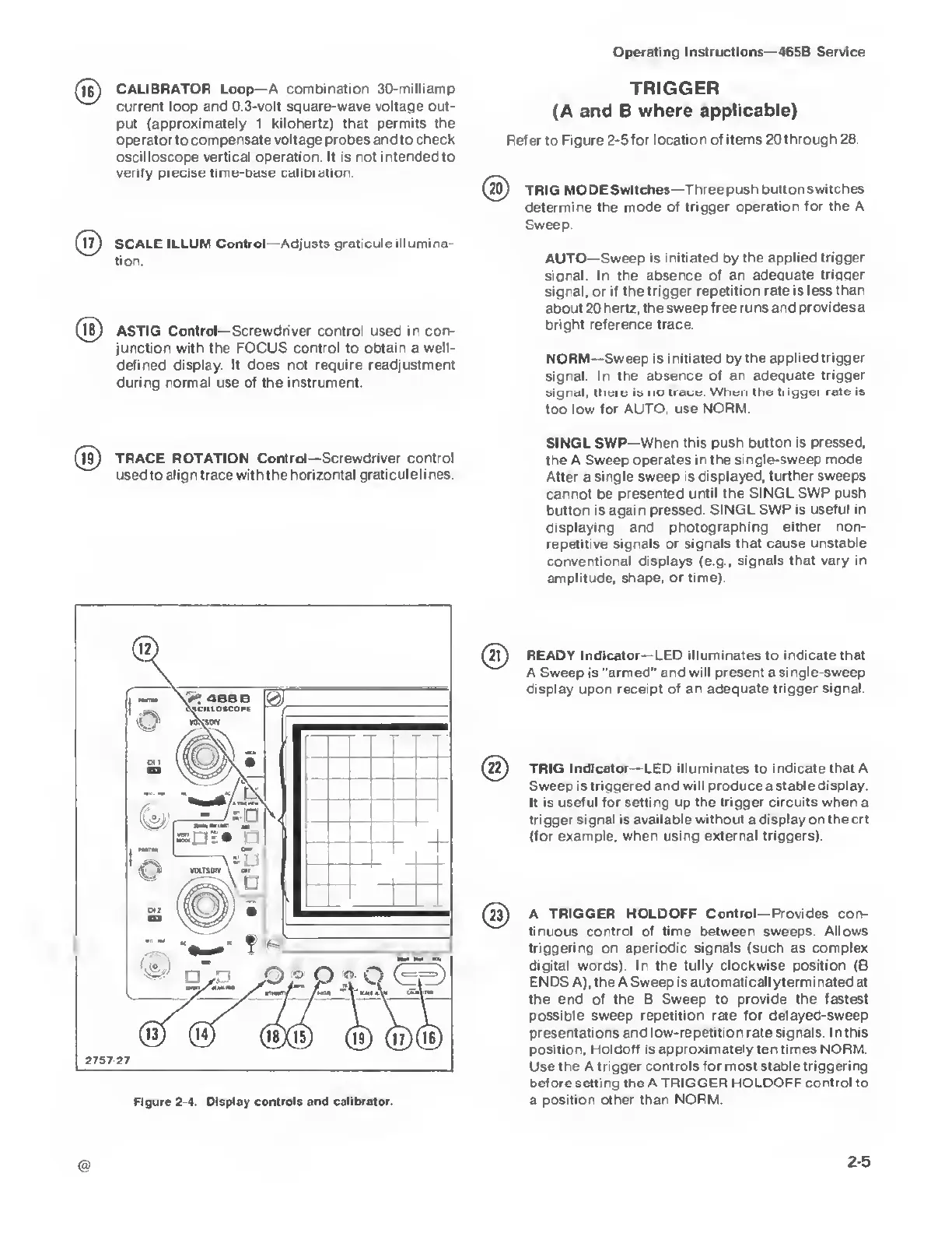
1BJ
CALIBRATOR Loop—A combination 30-milliamp
current loop and 0.3-volt
square-wave voltage out-
put (approximately 1
kilohertz) that permits the
operator to
compensate voltage probes and to check
oscilloscope vertical operation. It is not intended to
verify precise
time-base calibration.
SCALE
ILLUM Control —Adjusts graticule illumina-
tion.
(Tfi)
ASTIG Control—Screwdriver control used in
con-
junction
with
the FOCUS
control
to
obtain
a
well-
defined display It does not require readjustment
during normal use of the instrument.
(l9)
TRACE ROTATION Control—Screwdriver control
used to align trace with the horizontal
graticule
lines
TRIGGER
(A
and B
where applicable)
Refer to
Figure
2-5
for
location of items 20 through 28.
20)
TRIG MODE
Switches—Three push button
switches
determine the mode
of trigger operation for
the A
Sweep.
AUTO—Sweep is initiated by
the applied trigger
signal. In the absence
of an adequate triqqer
signal,
or
if the trigger
repetition rate is less than
about 20 hertz,
the sweep free runs and
provides
a
bright reference
trace.
NORM—Sweep
is initiated by the
applied trigger
signal In
the absence of an adequate
trigger
signal, there is no
trace.
When
the trigger rate is
too low for AUTO, use
NORM.
SINGL SWP—When
this push button is pressed,
the
A
Sweep
operates in the
single-sweep mode
After
a
single sweep is displayed,
further sweeps
cannot be presented
until the SINGL SWP push
button is again pressed.
SINGL SWP is useful in
displaying and
photographing either non-
repetitive signals or signals
that cause unstable
conventional displays (e.g., signals
that vary in
amplitude,
shape, or time).
READY Indicator—
LED illuminates to indicate that
A Sweep is
"armed" and will present a single-sweep
display upon receipt of an adequate trigger signal.
(22)
TRIG Indicator—LED
illuminates
to
indicate that
A
Sweep
is
triggered and will produce a stable display.
It is useful for setting up the trigger circuits when a
trigger signal is available without a display on the crt
(for example, when using external triggers).
A TRIGGER HOLDOFF Control— Provides con-
tinuous control of time between
sweeps. Allows
triggering on aperiodic signals (such as
complex
digital words). In the fully clockwise position (B
ENDS A), the A Sweep is
automatically terminated at
the end of the B
Sweep
to
provide the fastest
possible sweep
repetition
rate
for delayed-sweep
presentations and
low-repetition rate signals.
I
nthis
position,
Uoldoff is approximately ten times NORM.
Use the A trigger
controls for most stable triggering
before setting the A TRIGGER HOLDOFF
control
to
a
position other than NORM.
2-5