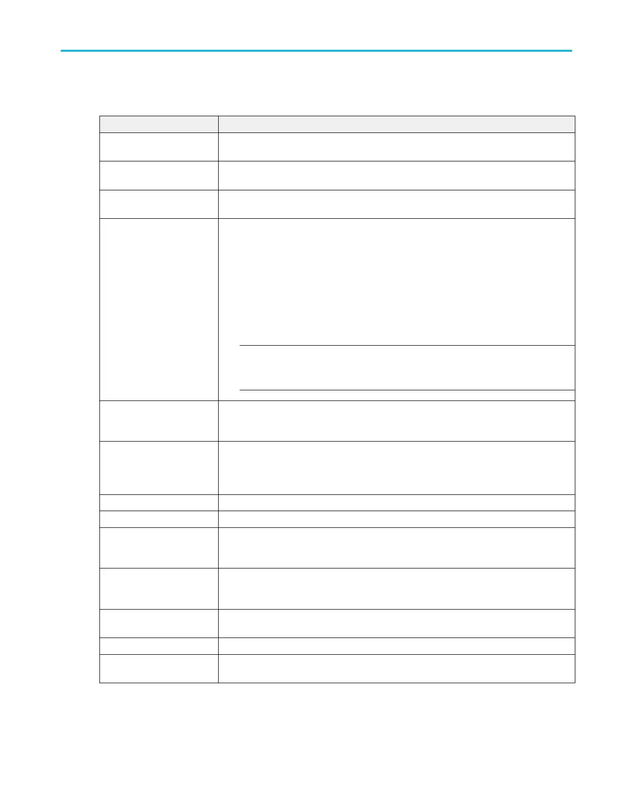
Switching Loss measurement: Configure panel.
Field or control Description
Voltage Source Selects the voltage source used to take the measurement. Tap the field to show the list of
available sources.
Current Source Selects the current source used to take the measurement. Tap the field to show the list of
available sources.
Label Sets the name of the measurement. You can use the default name, or double-tap in the field
and change the label using a connected keyboard or the virtual keyboard.
Type Select SMPS / PFC/ Flyback:
■
SMPS: Select this option in case of signals without noise and ringing. The Vg source is not
required. Select Vg source (Source 3), in case of noisy signal.
■
PFC: Select this option when input DUT signals are from Power Factor Correction Circuit.
For this case, Vg source is mandatory.
■
Flyback: Select this option when input signals are ringing. This option does not require a
Vg source.
NOTE. Displayed REF levels shown in the Reference Levels panel after selecting Flyback
are default values and not the internally computed REF values used for measurement
calculations.
Gate Voltage (Vg) Sets the Vg input source, which is a clean signal.
Available when Type = SMPS or PFC.
Vg Level Ton - Start Selects the source of computation of the harmonic. In the voltage source, standard is always
None.
Available when Gate Voltage (Vg) ≠ None.
PWM Type Select Fixed or Variable based on the varying pulse width of the switching signal.
Conduction calculation Select MOSFET or BJT/IGBT semiconductor types.
R
DS
(on) If MOSFET is selected, then R
DS
(on) is used to compute for conduction Loss.
Available when Conduction Calculation = MOSFET
V
CE
(sat) If BJT/IGBT is selected, then V
CE
(sat) is used to compute for conduction loss.
Available when Conduction Calculation = BJT/IGBT.
Set On/Off Levels In: Sets the REF levels for computation of the T
ON
and T
OFF
regions. Levels can be set in % or
absolute values.
T
off
-Stop Current Level Sets the T
on
-Start and T
off
-Stop of the max switch current.
T
on
-Stop & T
off
- Start Voltage
Level
Sets the voltage level value for T
off
-Stop and T
on
. Can be entered as a percent or as a voltage,
depending on the setting of the Set On/Off Levels In: control.
Menus and dialog boxes
MSO54, MSO56, MSO58, MSO58LP, MSO64 Help 179
 Loading...


