Brief procedures
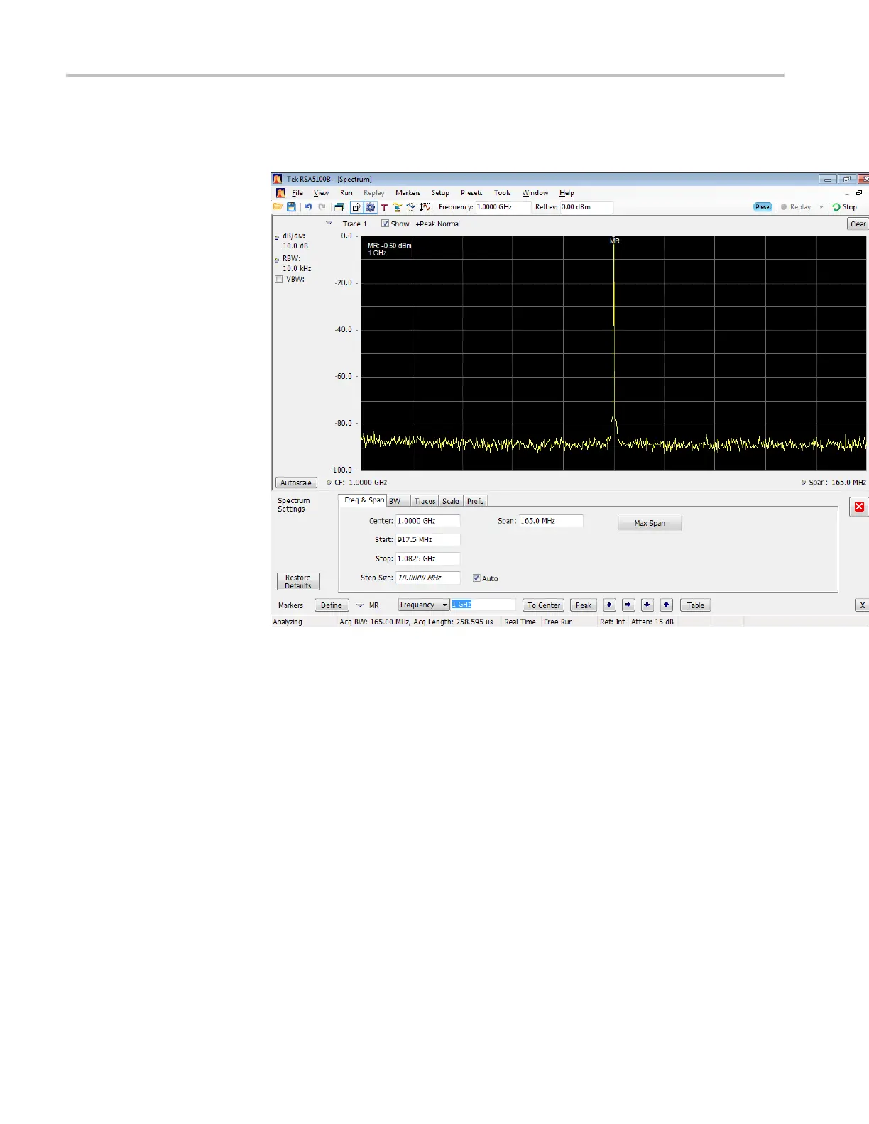
16. Check that the C
hannel 1 waveform is properly displayed on the signal
analyzer screen. (See Figure 2-8.)
Figure 2-8: 1 GHz output waveform – Filter set to Low Pass
17. Press the All Outputs button to disable the outputs.
18. Click the Setup tabonthedisplay.
a. Set Filter to Band Pass
b. Set
Range to 10–14.5GHz
19. Press the Home button, or click the Home tab on the display.
20. In the Waveform List window, select (drag and drop) the Waveform_11 GHz
waveform on to the work space.
21. Press the All outputs off button to enable the outputs.
22. Check that the Channel 1 waveform is properly displayed on the signal
analyzer screen. (See Figure 2-9.)
2–16 AWG70000A Series and AWGSYNC01 Technical Reference

 Loading...