Performance tests
Analog amplitude accuracy
NOTE. If checking an AWG70001A instrument with Option AC, ensure that
Channel 1 is se
t to Direct Mode in the Setup tab to enable the analog + and –
complimentary outputs.
Required equipment Prerequisites
Digital multimeter
BNC-dual banana adapter
50 Ω BNC termination
SMA female-BNC male adapter
50 Ω SMA termination
(See page 2-21, Prerequisites.)
Measure the termination resistance. Before verifying the analog amplitu
de
accuracy, you need to measure the resistance of t he 50 Ω BNC t ermination.
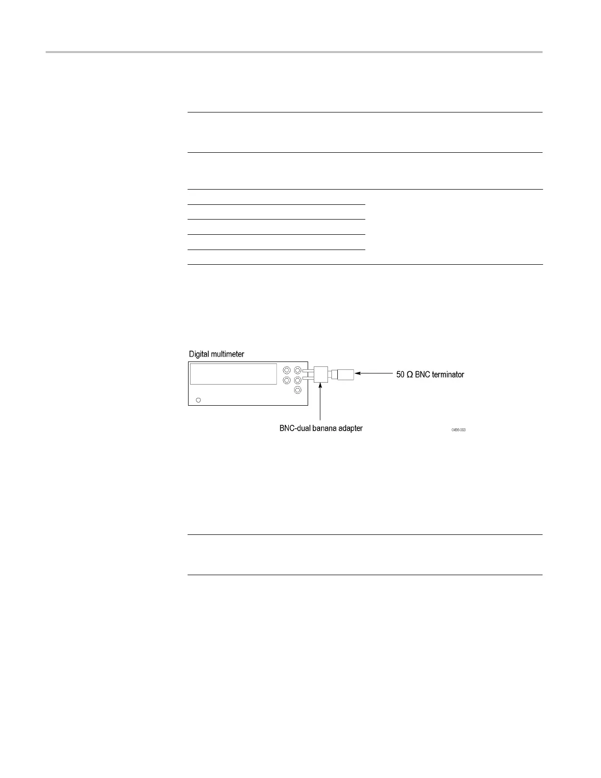
1. Connect the BNC-dual banana adapter and 50 Ω BNC termination to the HI
and LO inputs on the digital multimeter.
Figure 2-13: Equipment connection for measuring the termination resistance
2. Set the digital multimeter to the Ω 2wiresmode.
3. Measure the resistance and note the value as Term_R.
4. Set the digital multimeter to the DCV mode.
NOTE. Lead resistance is not included in the measurement results when using
four wire ohms. The accuracy is higher especially for small resistances. Use a
four wire method if necessary.
Check the analog amplitude accuracy.
1. Press the All Outputs On/Off button on the instrument to turn off all the
outputs.
2. Connect an SMA-BNC adapter to the 50 Ω BNC termination on the digital
multimeter.
2–24 AWG70000A Series and AWGSYNC01 Technical Reference

 Loading...