Brief procedures
Checking the A
Coutput
(AWG70001A with option
AC)
Required equ ipment Prerequisites
Signal analyzer
One P lanar Crown RF Input Connector –
7005A-1 SMA Female
One 50 Ω SMA cable
Two 50 Ω SMA terminations
None
1. Press the All Outputs button on the instrument to turn off all the outputs.
2. Click the Reset to default setup button in the toolbar.
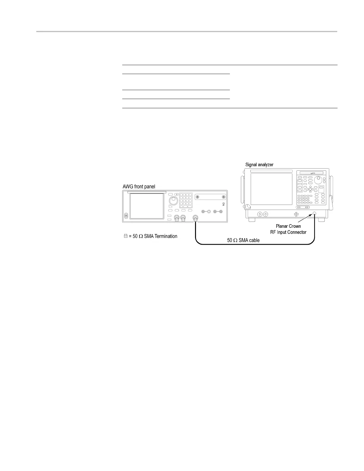
3. Usea50Ω S
MA cable to connect the AC connector on the instrument to
the RF input of the signal analyzer.
Figur
e 2-6: Equipment connections for checking the AC output
AWG70000A Series and AWGSYNC01 Technical Reference 2–13

 Loading...