Performance Verification
Table 81: Image suppression settings (cont.)
RSA5100B Center Frequency RF Generator Output Frequency (Image)
23 GHz 18.6 GHz
25 GHz 16.6 GHz
NOTE. The intent of the image spurious test is to measure spurious responses
caused by the injection of an external signal that would induce an image product
on the display. These images can be the same frequencies as residual spurs. In
case of question, slightly change the frequency of the input signal to induce a
corresp
onding change in the displayed frequency o f the image spur. Change
the input frequency in steps that allow the product to stay within the on-screen
frequency span. If the on-screen spur does not move in response to the input signal
change, it is not an image and is not covered in the image spurious specification.
Some care must be taken in noting the frequency change. The images specified in
the specification are 1:1 images and they will move -1:1 with changes in input
signa
l fre quency. Never discount the possibility that a spur in question c ould be
coming from the test signal generator. Such spurious responses can also move
with changes in signal generator frequency. In case of question, validate the
performance of the generator with a different Signal Analyzer and/or filter the
signal from the test generator to remove unwanted products.
If the spur seen o n screen is a residual, it will still be present with the input to the
signal analyzer terminated in 50 ohms. Residual spurs are subject to separate
specification limits.
Spurious Response with
Signal
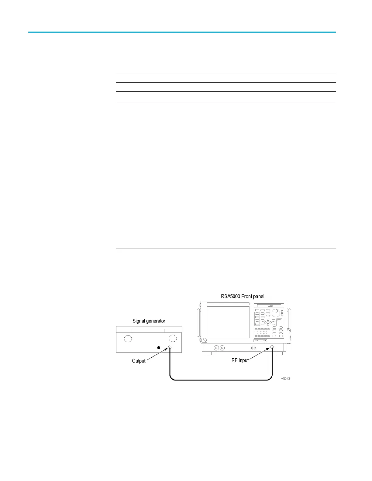
1. Connect the RF generator to the RSA5100B RF Input, as shown in the
following figure.
Figure 16: Equipment connections for Signal Spurious check
2. Reset the RSA5100B to factory defaults: select Setup > Preset (Main).
3. Select Tools > Alignments and select Align Now.
128 RSA5100B Series Technical Reference
 Loading...


