OPERATING
INSTRUCTIONS
Section 2—T912
OPERATING
VOLTAGE
WARNING
To prevent electric
shock,
do not remove
instrument
cover. Refer
servicing to
qualified
personnel.
Your instrument
will
operate from either a 120 V or
240 V ac 50
to
60
Hz nominal power input source. Check
that
the
Power Input
Voltage
Selector (120V/240 V)
switch and the Regulating Range Selector (HI/LO)
switch
are set
to
positions that include the value of the applied
power input
voltage.
In the United States,
the
120 V/240 V
switch is normally set for 120 V and the HI/LO switch is
normally
set for
HI
at the factory. In Europe, the
120 V/240 V switch is set for
240
V and the HI/LO switch
is
normally
set for LO. The POWER
indicator lamp will blink
when the applied power input voltage varies more than
about
10%
(either high or low) from the
value
for which the
switches are set.
^
CAUTION <
Your
instrument may be damaged
if it is operated
from
a
240
V power input voltage source with the
120 V/240 V switch set for 120 V.
The 120
V/240 V
switch and the
HI/LO
switch are both visible from the
bottom
of the instrument In all
T900-series
bench
version
oscilloscopes, but
the
120
V/240 V switch is
not
adjustable from outside
of
the
cabinet. Refer
120 V/240 V power input voltage selection to
qualified service personnel.
FUNCTIONS OF CONTROLS,
CONNECTORS,
AND
INDICATORS
Before
you
turn
the
instrument
on,
read this portion of the
manual
to
familiarize yourself with the controls, connec-
tors,
and indicators.
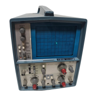
A. DISPLAY
Front Panel (Fig.
2-1)
INTENSITY—Adjusts the brightness
of
the crt dis-
play. Set for the lowest visible display
to
prolong crt
life.
FOCUS—
Adjusts
for optimum
spot
size
and
defini-
tion.
BEAM FINDER—
Locates
off-screen
displays. Com-
presses the crt display to within the graticule area
independently of the position control or applied
signals.
To
locate
an
off-screen display:
a. Set the vertical POSITION and INTENSITY
controls to
midrange and rotate the horizontal
POSITION control clockwise.
b. If a display or dot
still
is not visible, press BEAM
FINDER
and
hold in.
A
compressed display
or dot
should appear.
If not, increase the
INTENSITY
until
a
display appears.
If a dot
or vertical
line
appears, the sweep is not
triggered. Set the trigger
MODE
switch
to
AUTO to
obtain a display. Use the vertical and horizontal
POSITION controls to move the display near the
center of the graticule. Release
the BEAM
FINDER
button and
adjust
the trigger level
control for a
stable display.
If
a
compressed display
appears, adjust the
VOLTS/DIV switch and the horizontal and vertical
POSITION controls for a stable display.
The T912
has
a 3-wire cord with a 3-terminal polarized
plug for connection
to the
power source and
safety-earth.
The ground
terminal
of the
plug
is directly connected to
the metal
parts of the
instrument. For electric-shock
protection, insert this
plug
in a mating outlet with asafety-
earth
contact.
STORE—Selects storage mode (pushbutton in) or
non-store
(pushbutton
out) conventional os-
cilloscope operation.
ERASE—Press to erase a
stored display
REV C,
MAR 1979
2-1
 Loading...