Adjustments—T91
2
B. VERTICAL AMPLIFIER
Equipment
Required
1, Digital Voltmeter
6.
Low
Capacitance Alignment Tool
2. Amplitude Calibrator
7.
Screwdriver
3. Square-Wave Generator
8. 10X Probe
4. 50
n BNC
Termination
9. 10X
Attenuator
5. 50
O BNC
Cable
10.
Probe-tip-to-BNC
Adapter
Preliminary Control
Settings Set all other
controls
as
desired.
Set; ENHANCE
LEVEL fully ccw
INTENSITY
midrange (for visible
trace)
STORE
nonstore (button out)
FOCUS
midrange
Vertical
Mode
CH
1
VOLTS/DIV (both)
2
mV (IX)'
AC-GND-DC
(both) GND
VAR (both)
detent (cw)
SEC/DIV
.5 ms
X1-X10
XI (fully ccw
detent)
SOURCE INT
MODE
AUTO
SLOPE
TOUT
LEVEL midrange
POSITION
(all)
midrange
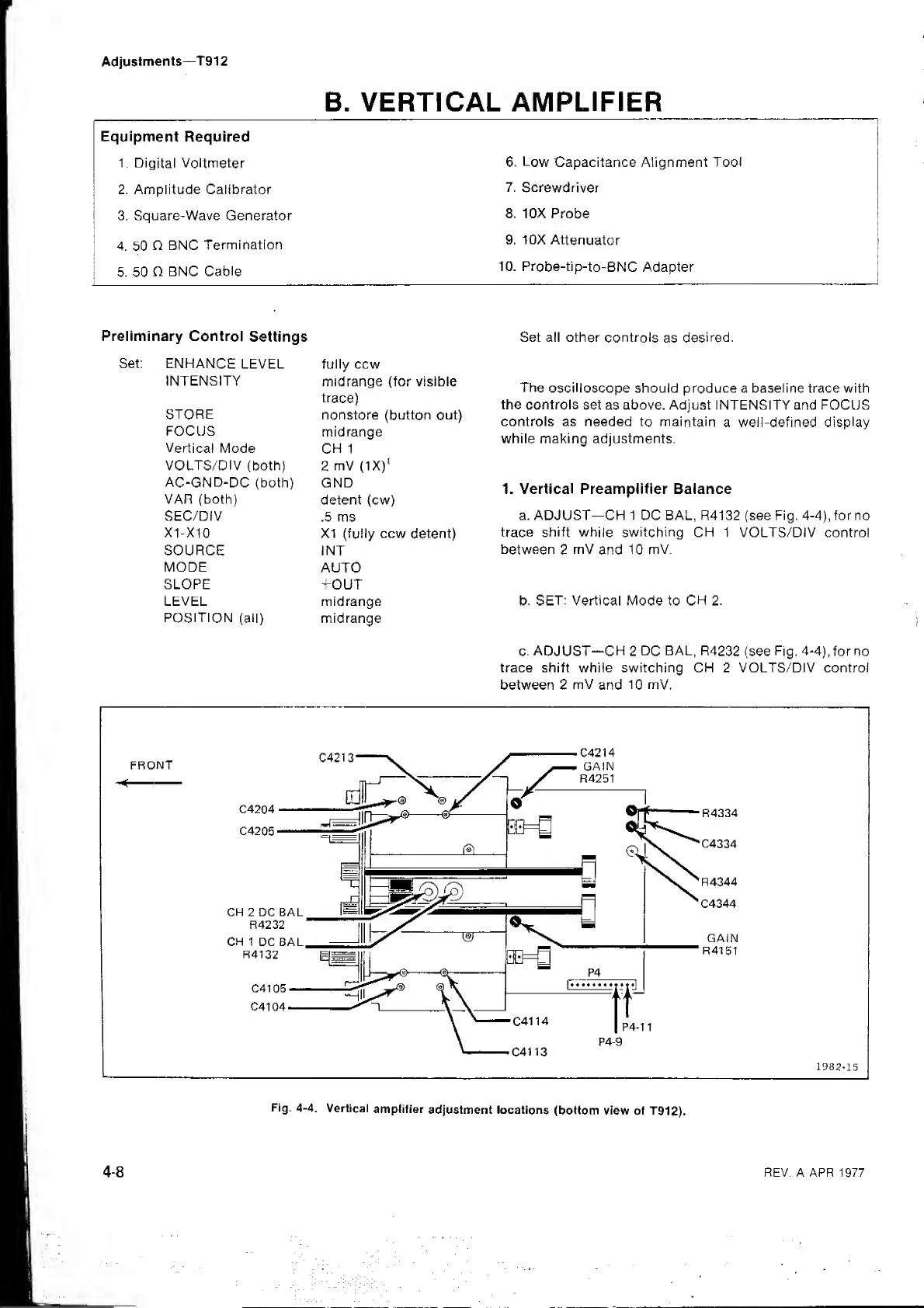
c.
ADJUST-CH
2
DC
BAL, R4232
(see
Fig.
4-4), for no
trace shift while switching CH 2 VOLTS/DIV control
between 2
mV
and
10
mV,
The
oscilloscope
should produce a baseline trace with
the controls
set as above. Adjust INTENSITY and FOCUS
controls as needed
to maintain
a well-defined
display
while making adjustments.
1. Vertical Preamplifier Balance
a. ADJUST—CH 1 DC BAL, R4132 (see Fig. 4-4),forno
trace shift while switching
CH 1 VOLTS/DIV control
between
2
mV
and 10
mV.
b. SET: Vertical Mode to CH 2.
REV. A APR 1977
 Loading...