Operating Instructions—T912
Channel
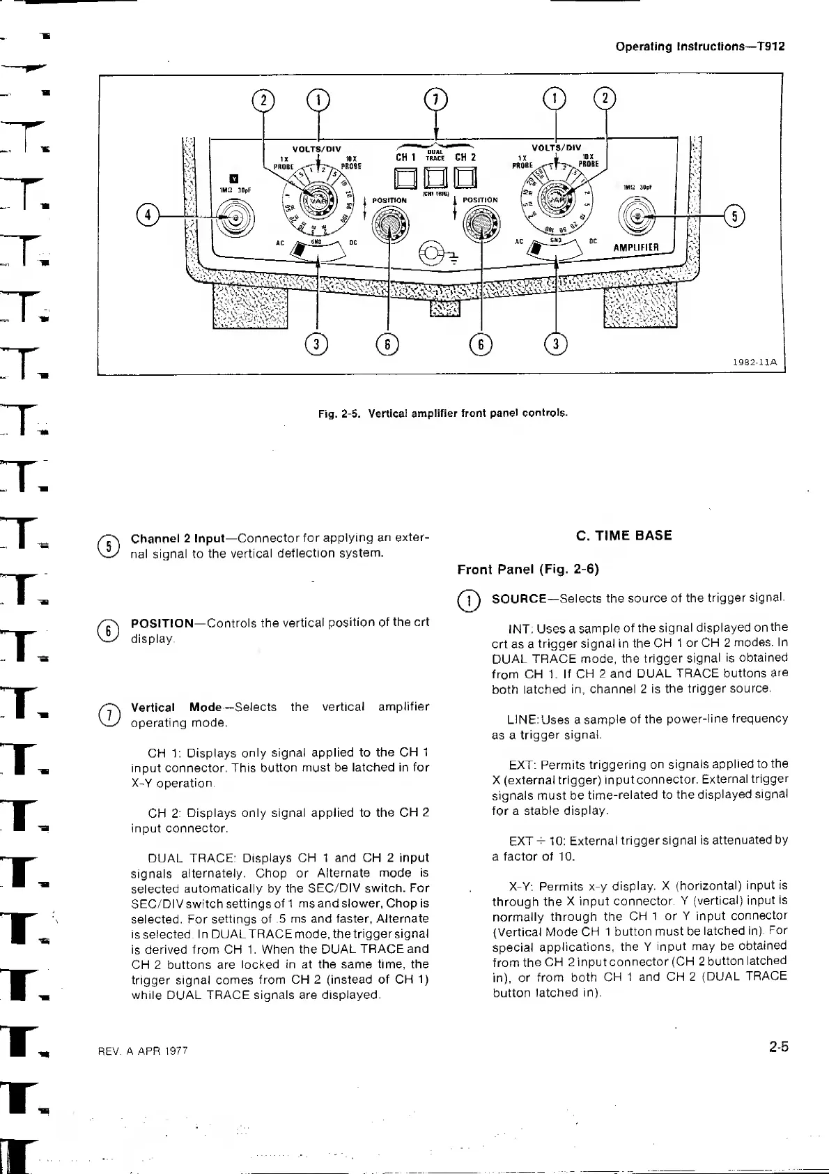
2 Input—
Connector
for applying
an
exter-
nal signal to the
vertical
deflection
system.
©
POSITION—
Controls the vertical
position of
the crt
display.
Vertical
Mode—Selects the
vertical
amplifier
operating
mode.
CH 1: Displays
only signal applied to the
CH
1
input connector. This
button
must be latched in for
X-Y operation
CH
2: Displays only signal applied to the
CH
2
input connector,
DUAL TRACE:
Displays CH
1 and CH 2 input
signals
alternately. Chop or
Alternate mode
is
selected
automatically by the
SEC/DIV switch. For
SEC/DIV switch settings
of
1
ms
and slower, Chop is
selected. For
settings of
.5 ms and faster, Alternate
isselected.
In DUALTRACEmode,
thetriggersignal
is
derived from CH 1 . When the
DUAL
TRACE and
CH 2 buttons are
locked
in at the same time, the
trigger signal comes
from CH
2
(instead of CH
1)
while DUAL TRACE signals are displayed.
C.
TIME
BASE
Front
Panel
(Fig.
2-6)
SOURCE—
Selects the
source of the
trigger
signal.
INT . Uses a
sample
of the
signal
displayed on
the
crt as a
trigger signal in
the CH
1 or CH 2
modes. In
DUAL
TRACE mode,
the trigger
signal
is
obtained
from CH 1,
If CH
2 and
DUAL TRACE buttons
are
both latched
in, channel 2 is
the trigger source.
LINE:
Uses a
sample
of the
power-line
frequency
as a
trigger signal.
EXT:
Permits
triggering
on
signals
applied to
the
X (external trigger)
input
connector.
External
trigger
signals must be
time-related to the
displayed
signal
for a stable
display.
EXT 10: External
trigger signal is
attenuated
by
a factor of 10.
X-Y: Permits x-y
display. X
(horizontal)
input is
through the
X input
connector.
Y
(vertical) input
is
normally
through the
CH
1 or Y input
connector
(Vertical Mode
CH
1 button must be
latched in).
For
special
applications, the Y
input
may be
obtained
from
the
CH 2 input
connector
(CH 2
button
latched
in),
or
from both
CH
1 and CH
2
(DUAL
TRACE
button
latched in).
REV.
A APR
1977
2-5
 Loading...