Operating lnstructions~T912
UX
9
U
VERTICAL
DEFLECTION
1907-27
Fig.
2-9.
Peak-to-peak voltage measurement.
Instantaneous Amplitude Measurement
The following procedure
explains how to measure the
amplitude of any
point
on a waveform with
respect to
ground.
1.
Set the
AC-GND-DC
switch to DC.
2.
Apply the signal to be measured to one of the vertical
input connectors.
Set
the Vertical
Mode switch
to select
the channel used.
KK
9
1
:
pp^
IIW
1
n
m
ii
1
H
in
1 n
1
innmmy
a
n
I u
REFERENCE
LINE
1907-28
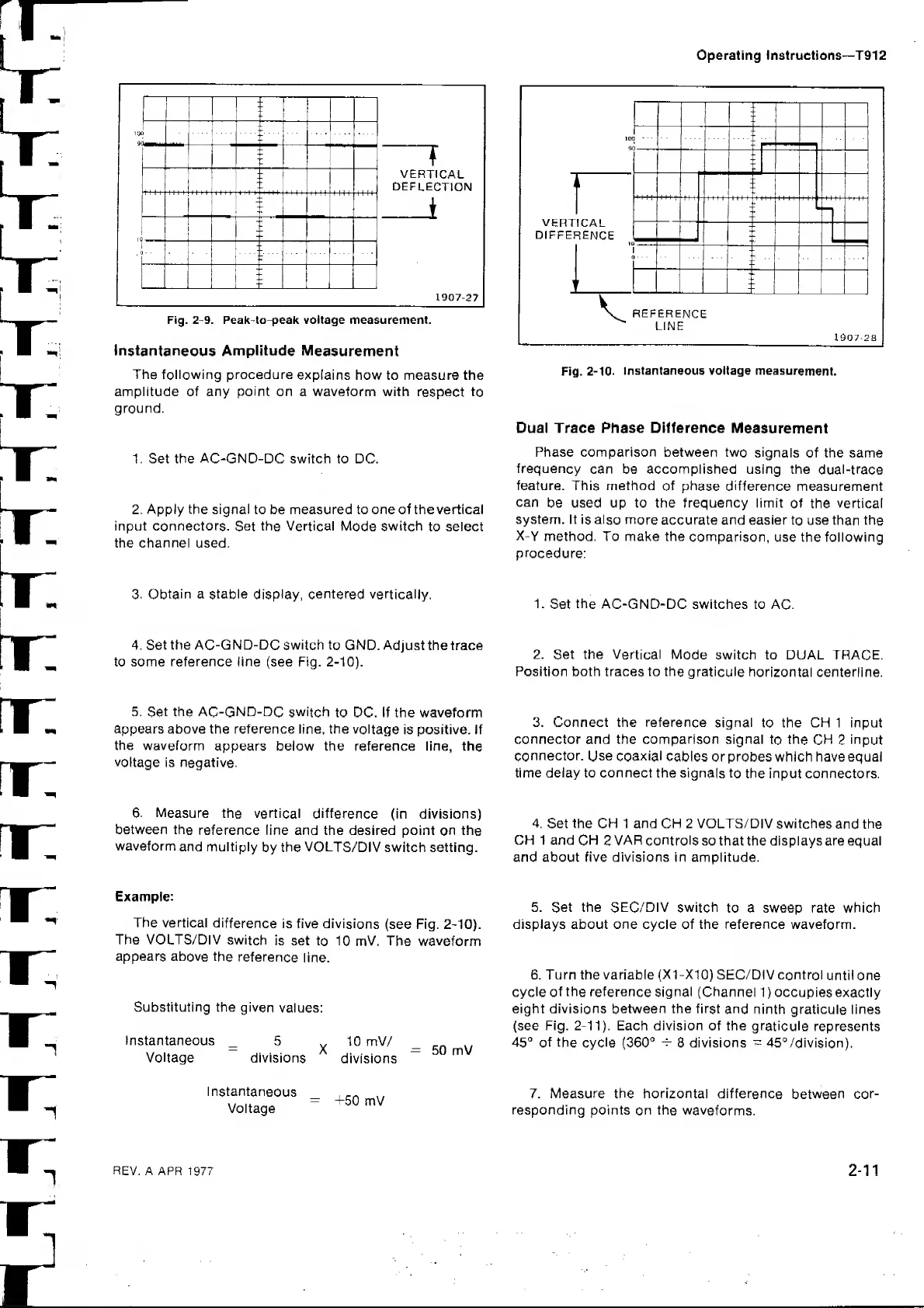
Fig.
2-10. Instantaneous voltage measurement.
Dual Trace Phase Difference
Measurement
Phase comparison between two
signals
of the same
frequency
can be accomplished using the
dual-trace
feature. This method
of phase difference
measurement
can
be used up to the frequency limit
of
the
vertical
system, it
is also more
accurate and easier
to
use
than
the
X-Y
method. To make the
comparison,
use the following
procedure:
3.
Obtain
a stable
display, centered vertically.
1.
Set
the
AC-GND-DC switches to
AC.
4.
Set
the AC-GND-DC
switch to GND. Adjust
thetrace
to some reference line (see Fig. 2-10).
5.
Set
the AC-GND-DC
switch
to DC. If the waveform
appears above the reference line, the
voltage
is positive. If
the
waveform
appears below the reference line, the
voltage
is negative.
6.
Measure
the vertical
difference
(in divisions)
between the
reference line and the desired point
on
the
waveform
and multiply
by the
VOLTS/DIV
switch setting.
Example:
The vertical
difference
is five divisions
(see Fig.
2-10).
The VOLTS/DIV
switch
is set
to 10
mV,
The waveform
appears above
the
reference
line.
Substituting the
given
values:
Instantaneous
_
5
X
Voltage
divisions
divisions
Instantaneous
,
,,
Voltage
=
+5*^
2.
Set the
Vertical Mode
switch to DUAL TRACE.
Position both traces to the
graticule
horizontal centerline.
3.
Connect the reference signal
to the CH 1 input
connector and the comparison signal
to the CH
2
input
connector.
Use coaxial
cables or probes which have equal
time delay to connect the
signals to
the input connectors.
4,
Set the CH 1 and CH 2 VOLTS/DIV switches
and the
CH 1 and
CH
2
VAR
controls
so that the displays are equal
and about five divisions in amplitude.
5.
Set the SEC/DIV
switch
to a sweep rate which
displays about one cycle of the reference waveform.
6. Turn the variable
(X1-X10)
SEC/DIV control
until one
cycle of
the
reference signal (Channel
1
)
occupies exactly
eight divisions between the first
and
ninth graticule lines
(see Fig.
2-11).
Each division of the
graticule
represents
45°
of the cycle
(360°
^
8 divisions
~
45°/division),
7.
Measure
the horizontal difference
between cor-
responding points
on
the
waveforms.
REV.
A APR 1977
2-11
 Loading...