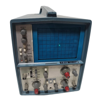
Performance Check—T912
7. 1 MHz Internal Triggering
11. Z-Axis Input
a.
Connect test equipment as shown in Fig.
3-3.
a. Set: CH 1
VOLTS/DIV
1 V
SEC/DIV
.1 ms
b. Set: CH 1 VOLTS/DIV 1 V
SOURCE INT
SEC/DIV
.5
fjs
Trigger Mode
AUTO
X1-X10
XI (fully ccw
detent)
X1-X10 (Variable) XI
(fully
ccw
detent)
c. Set sine-wave generator
frequency
for
1
MHz and
sine-wave generator frequency to
50
kHz and
adjust
output
amplitude
for a 0.5-division display.
adjust output amplitude for
a
5-division
display.
d. CHECK—Stable display can be obtained in both the
+OUT and -IN
positions of the SLOPE
switch for both
AUTO and NORM.
c. Disconnect 50 0 cable from
X
(or EXT, external
trigger)
input,
and connect it to
EXT Z AXIS
connector
at
rear of instrument.
8. 1 MHz External Triggering
a. Set: CH 1 VOLTS/DIV .1 V
b. Adjust sine-wave generator output amplitude for
100 mV (one division on crt).
d. CHECK—Trace modulation is
noticeable
at
normal
intensity. (Adjust LEVEL control as required to obtain
stable display.)
e. Disconnect test setup.
c.
Set: SOURCE EXT
d.
CHECK—
Stable display
can be obtained in both the
-LOUT
and —IN positions of the SLOPE switch for
both
AUTO
and NORM.
9. 10 MHz Internal Triggering
a. Set;
SOURCE
INT
CH
1 VOLTS/DIV
50
mV
X1-X10
X10 (fully
cw
detent)
b.
Set
sine-wave generator
frequency
for
10 MHz and
output amplitude for a 3-division display; then
set CH 1
VOLTS/DIV
to .1
V.
c. CHECK—Stable display can be obtained in both the
LOUT
and
-IN
positions
of the SLOPE switch for both
AUTO
and NORM modes.
10.
10 MHz External
Triggering
a. Set:
SOURCE EXT
b.
CHECK—Stable
display
can be obtained in both the
-LOUT
and
—IN
positions of the
SLOPE
switch for both
AUTO
and NORM.
12. Low Frequency Triggering
a. Set: SEC/DIV 10
ms
X1-X10
(variable) XI
(fully
ccw
detent)
VOLTS/DIV
(CH
1)
2 mV
Channel 1
AC-GND-DC
DC
MODE
NORM
b.
Connect
10X
probe to CH 1 input.
c. Lay probe near ac line voltage
source and adjust
CH 1 VOLTS/DIV switch and VAR control
for a
0.4-
division
display.
d.
CHECK—Stable display
can be obtained in
both the
-rOUT and —IN positions of the
SLOPE
switch for AUTO
and NORM modes, and LINE and I NT
SOURCE
positions.
e.
Remove probe.
f. Return VAR
to detent; MODE
to NORM; and
SOURCE
to INT.
3-6
REV.
B JUL 1977
 Loading...