Adjustments—
T91
2
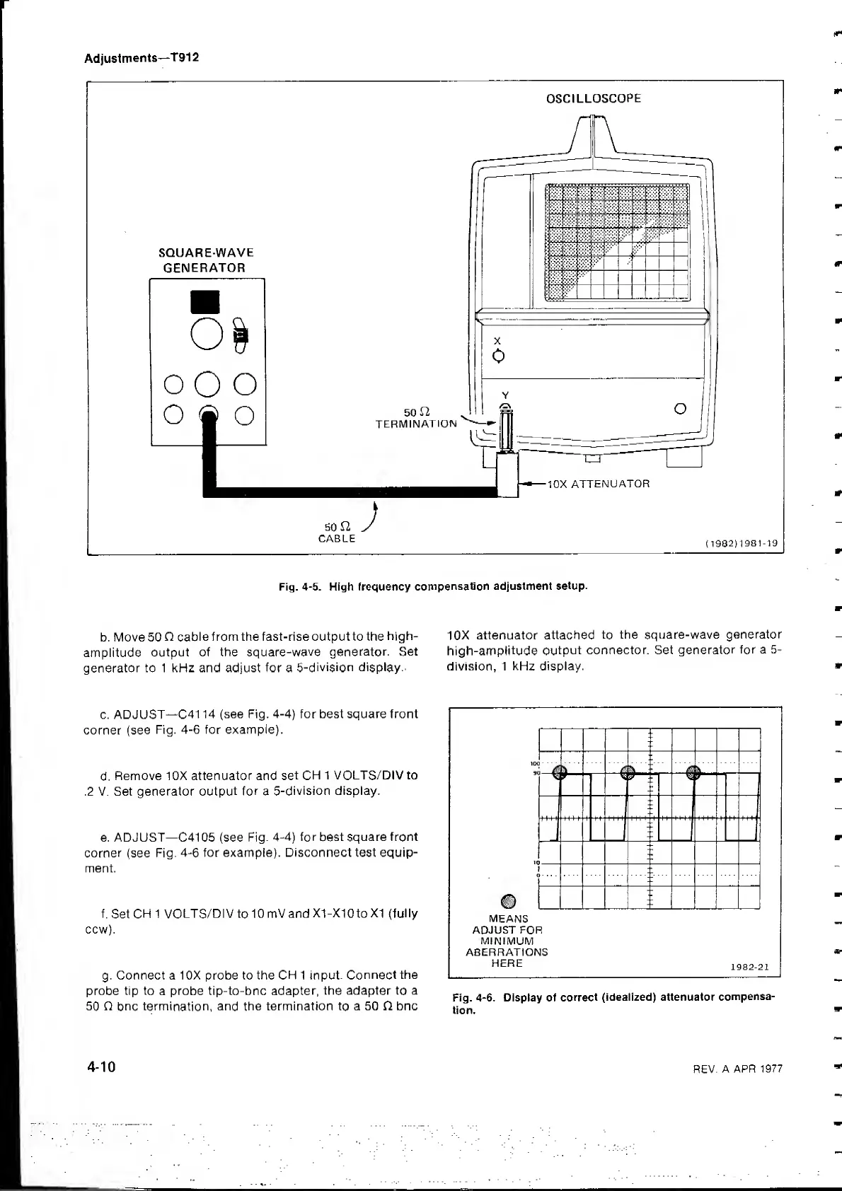
SQUARE-WAVE
GENERATOR
OO
O
o
®
o
OSCILLOSCOPE
50
TERMINATION
-10X
ATTENUATOR
SO
n
CABLE
(
1932
)
1981-19
Fig.
4-5.
High frequency
compensation
adjustment
setup.
b. Move 50
O
cable
from the fast-rise output to the
high-
amplitude
output of the
square-wave generator.
Set
generator to 1 kHz and adjust for a
5-division display.'
10X attenuator attached
to
the square-wave
generator
high-amplitude
output
connector. Set
generator
for a
5-
division, 1
kHz display.
c. ADJUST—
C41
14
(see Fig. 4-4) for best square front
corner (see
Fig.
4-6
for example).
d.
Remove 10X attenuator and
set CH
1 VOLTS/DIV to
.2 V. Set generator
output for
a
5-division display.
e. ADJUST—C41
05
(see Fig. 4-4)
for
best
square front
corner
(see Fig.
4-6
for example). Disconnect test equip-
ment.
f.
Set
CH 1
VOLTS/DI V
to
1 0 mV and
X1-X10
to
XI (fully
ccw).
g.
Connect a 10X probe to the CH 1 input.
Connect
the
probe tip to a probe tip-to-bnc
adapter,
the adapter
to
a
50 Q bnc termination,
and the termination
to
a 50 O bnc
MEANS
ADJUST FOR
MINIMUM
ABERRATIONS
HERE
Fig.
4-6.
Display of
correct
(idealized) attenuator
compensa-
tion.
REV.
A APR 1977