17
e. Notice that the LED next to the multipurpose control is lit. In this menu, you can turn the
multipurpose control to select the channel that will be the source of the trigger. Select channel 2
(and 3 and 4 in sequence if you are using a 4-channel oscilloscope) and note the effect this has
on the triggered state of the display. When channel 1 is not selected, the display is not triggered
because channel 2 (and 3 and 4 if you are using a 4-channel oscilloscope) do not have an
applied signal.
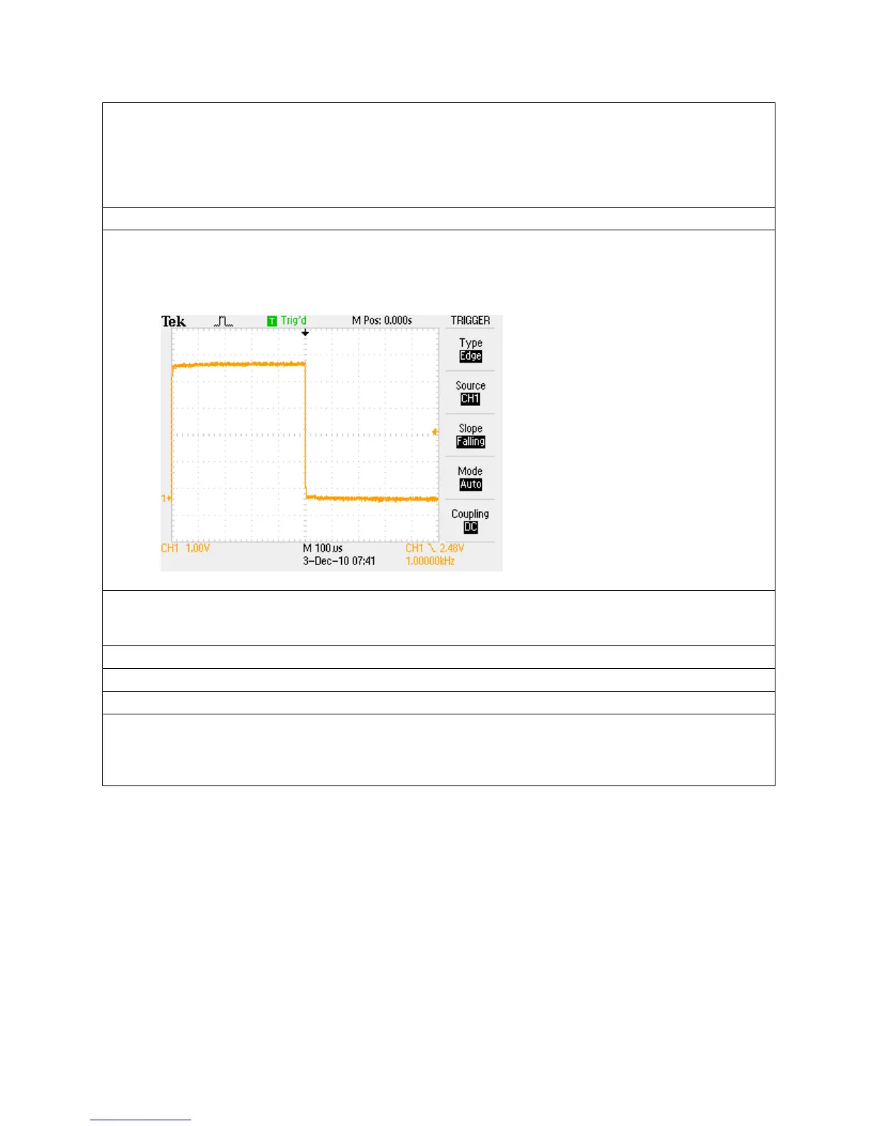
f. Turn the multipurpose control to select channel 1 and ensure the display is triggered.
g. Push the Slope side-bezel button to select the falling edge of the signal as the trigger point.
The slope selections control whether the trigger looks for a positive or negative edge on the
trigger signal.
2. The edge trigger is used by default. However, because the trigger is a critical element in making a
measurement, there are several trigger options to pick from based on your measurement needs.
Perform the following steps to see how a few of the other trigger types are used.
a. Push the Type side-bezel button for a selection of trigger types.
b. Push the Type side-bezel button until Pulse is selected.
c. Push the When side-bezel button to see your choices.
d. Push the When button until = is selected.
The pulse width = setting causes the oscilloscope to trigger when the pulse width is within +/-5%
of the specified values.

 Loading...