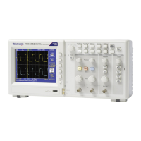
3. Connect the oscilloscope channel under test to the DC voltage source as shown in the following figure:
4. For each vertical scale (volts/division) setting in the following table, perform the following steps:
a. Set the DC voltage source output level to the positive voltage listed and then record the mean measurement as V
pos
.
b. Reverse the polarity of the DC voltage source and record the mean measurement as V
neg
.
c. Calculate V
diff
= V
pos
- V
neg
and compare V
diff
to the accuracy limits in the following table:
Vertical Scale (volts/div)setting DC voltage source output levels Accuracy limits for V
diff
5 mV/div +17.5 mV, -17.5 mV 33.6 mV to 36.4 mV
200 mV/div +700 mV, -700 mV 1.358 V to 1.442 V
2 V/div +7.00 V, -7.00 V 13.58 V to 14.42 V
5. Set DC voltage source output level to 0 V.
6. Disconnect the test setup.
7. Repeat steps 1 through 6 for all input channels.
Check bandwidth
This test checks the bandwidth of all input channels.
1. Set up the oscilloscope using the following table:
Push menu button Select menu option Select setting
Default Setup - -
Channel 1 Probe 1X
Acquire Average 16
Trig Menu Coupling Noise Reject
Performance verification
16 TBS1000C Series Specification and Performance Verification
 Loading...