Performance Verification
4–8
TDS 200 Series Digital Oscilloscope Service Manual
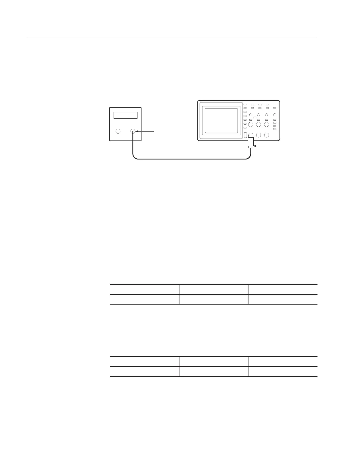
2. As shown below, connect the instrument channel selected in the table to the
leveled sine wave generator.
Digitizing oscilloscope
Leveled
sine wave
generator
50 W feedthrough
terminator
BNC cable
Output
3. Set the leveled sine wave generator frequency to 60 MHz if you are checking
a TDS 210 or to 100 MHz if you are checking a TDS 220 or TDS 224.
4. Set the instrument VOLTS/DIV to 500 mV/div.
5. Set the instrument SEC/DIV to 10 ns/div.
6. Set the leveled sine wave generator output level to approximately 750 mV
p-p
so that the measured amplitude is approximately 750 mV. (The measured
amplitude can fluctuate around 750 mV.)
7. Press SET LEVEL TO 50%. Adjust TRIGGER LEVEL as necessary and
then check that triggering is stable.
8. Change the instrument setup using the following steps:
Press menu button Select menu item Select setting
TRIGGER Slope Falling
9. Press SET LEVEL TO 50%. Adjust TRIGGER LEVEL as necessary and
then check that triggering is stable.
10. Change the instrument setup using the following steps:
Press menu button Select menu item Select setting
TRIGGER Slope Rising
11. Disconnect the test setup.
12. Repeat steps 1 through 11 until all input channels have been checked.

 Loading...


