Maintenance
TDS1000 and TDS2000 Series Digital Storage Oscilloscopes Service Manual
6-- 25
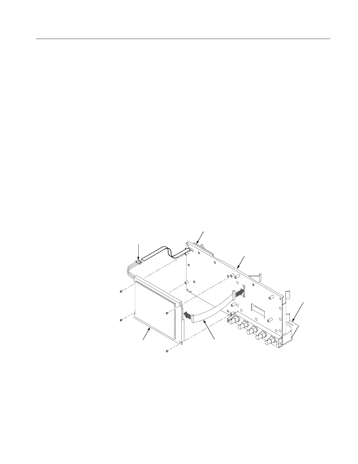
Installation. To install the display module, refer to Figure 6--15 and follow these
steps:
1. Reconnect the display cable at J201 on the main board by pushing the cable
straight down into the connector.
2. Route the display ribbon cable through the opening in the chassis. For more
information, see the display cable procedure on page 6--19.
3. Route the backlight cable through the opening in the internal assembly.
4. Install the four screws to attach the display module to the internal assembly.
The location of the screws will vary between color and monochrome
displays.
5. Reconnect the backlight cable to the power supply module. Connect to the
black socket for a monochrome LCD, and to the white socket for a color
LCD.
6. Use the installation procedure for each module removed to reassemble the
oscilloscope.
Backlight
cable
Power supply
module
Internal
assembly
Main
board
Display
ribbon cable
Display
module
Figure 6--15: Installing the display module
 Loading...

