Maintenance
TDS1000 and TDS2000 Series Digital Storage Oscilloscopes Service Manual
6-- 17
You will need a torque-limiting Torx T-15 screwdriver and a flat-blade screw-
driver for this procedure.
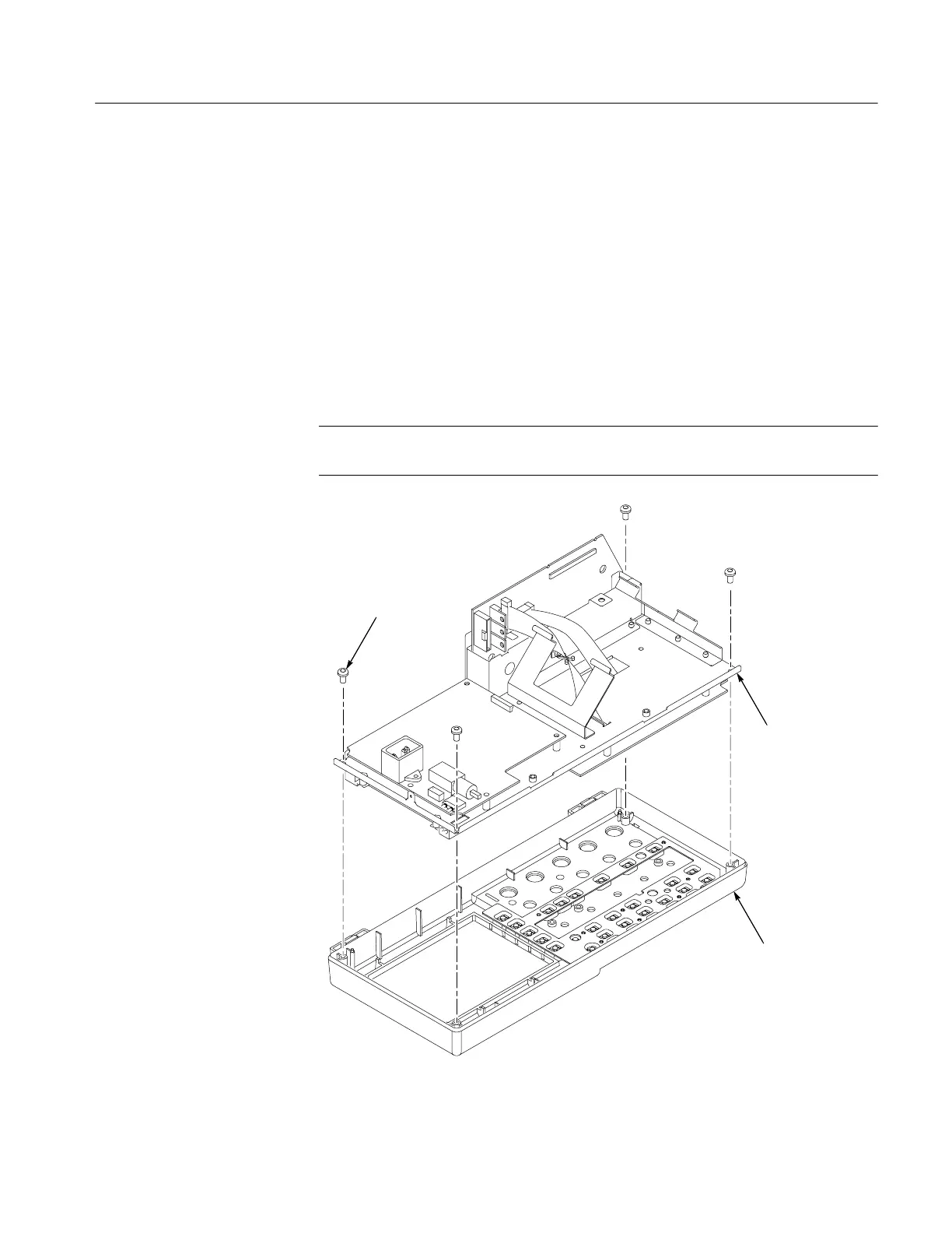
Removal. To remove the assembly, refer to Figure 6--9 and follow these steps:
1. Remove the front-panel knobs, power button, and rear case using the
procedures on page 6--10.
2. Remove the four screws attaching the internal assembly to the front case.
3. Lift the entire internal assembly (consisting of the chassis, all of the boards,
and the display screen) out of the front case.
NOTE. The switch keypad will most likely remain inside the front case. It does not
need to be removed with the internal assembly.
Remove screws (4)
Internal
assembly
Front case
Figure 6--9: Removing and installing the internal assembly
Internal Assembly
 Loading...

