Performance Verification
4-4
TDS1000 and TDS2000 S eries Digital Storage Oscilloscopes Service Manual
Press menu button Select settingSelect menu option
4. MEASURE
Source An unchecked channel
Type Mean
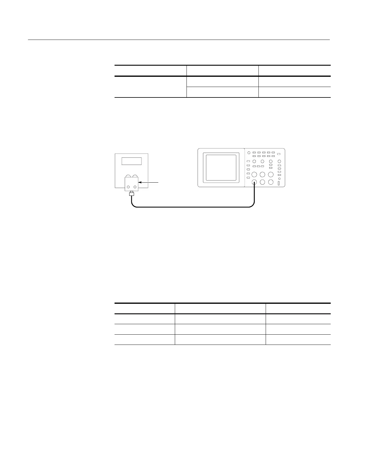
3. As shown below, connect the oscilloscope channel selected in the table to the
DC voltage source.
+--
DC voltage
source
Dual banana
to BNC
adapter
BNC cable
Digitizing oscilloscope
4. For each VOLTS/DIV setting listed below, perform the following steps:
a. Set the DC voltage source output level to the positive voltage listed and
then record the mean measurement as V
pos
.
b. Reverse the polarity of the DC voltage source and then record the mean
measurement as V
neg
.
c. Calculate V
diff
=V
pos
-- V
neg
and then compare V
diff
to the accuracy
limits in the table.
VOLTS/DIV setting DC voltage source output levels Accuracy limits for V
diff
5mV/div +17.5 mV, --17.5 mV 33.6 mV to 36.4 mV
200 mV/div +700 mV, --700 mV 1.358 V to 1.442 V
2V/div +7.00 V, -- 7.00 V 13.58 V to 14.42 V
5. Set DC voltage source output level to 0V.
6. Disconnect the test setup.
7. Repeat steps 1 through 6 until all input channels have been checked.
 Loading...

