EasyManuals Logo

Tektronix TDS2024 Manual

Tektronix TDS2024
139 pages
To Next Page IconTo Next Page
To Previous Page IconTo Previous Page
Page #94 background imageLoading...
Page #94 background image
Maintenance
TDS1000 and TDS2000 Series Digital Storage Oscilloscopes Service Manual
6-- 15
Use a torque-limiting Torx T-15 screwdriver and pliers for this procedure.
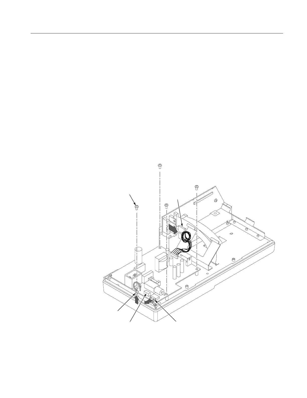
Removal. To remove the module, refer to Figure 6--7 and follow these steps:
1. Remove the power button and rear case using the procedures on page 6--10.
2. Disconnect the following wires:
H The ground wire on the power supply module from the chassis ground
lug.
H The two-conductor backlight cable on the power supply module.
H The power supply ribbon cable on the main board at J101. Press down on
the latch while pulling up on the cable.
3. Remove the four screws connecting the power supply module to the chassis
and lift the module from the internal assembly.
Remove screws (4)
Ground wire
Backlight cable
(color LCD)
Power supply
ribbon cable
Backlight connector
(monochrome LCD)
Figure 6--7: Removing the power supply module
Power Supply Module

Table of Contents

Other manuals for Tektronix TDS2024

Questions and Answers:

Question and Answer IconNeed help?

Do you have a question about the Tektronix TDS2024 and is the answer not in the manual?

Tektronix TDS2024 Specifications

General IconGeneral
Channels4
Bandwidth200 MHz
Sample Rate2 GS/s
Record Length2.5k points
Vertical Resolution8 bits
Vertical Sensitivity2 mV/div to 5 V/div
Timebase Range5 ns/div to 50 s/div
Display Resolution320 x 240 pixels
Math FunctionsAdd, Subtract, Multiply, Divide, FFT
Input CouplingAC, DC, GND
Trigger ModesAuto, Normal, Single
Trigger TypesEdge, Video, Pulse
ConnectivityUSB
Input Impedance1 MΩ
Maximum Input Voltage300 V
InterfaceUSB
Power Supply100 to 240 V
Dimensions326 mm x 158 mm x 124 mm

Related product manuals