Adjustment Procedures
TDS3000B Series Service Manual
5-5
During the procedure a fast rise step signal needs to be applied simultaneously to
all channels. A typical on-screen instruction might read:
Apply --2.2 V to 0 V (unloaded), fast-rise signal (
≤1ns)
to all channels.
Use the Applying DC Voltage to Input C hannels equipment setup shown on
page 5--3.
NOTE. Make sure to set the generator source impedance to 50 ohms.
Set the fast-rise signal repetition rate to anywhere between 100 Hz and 1 MHz,
inclusive.
The fast-rise signal Pk-Pk range is -2.2 V to 0 V (unloaded). Measure the
fast-rise signal, using an independent device with an input termination set to
1MΩ or greater, to verify that the fast-rise signal does vary between --2.2 V and
0 V, regardless of the generator’s programmed value. T his ensures that there is
enough signal range to adjust either 2-channel or 4-channel oscilloscopes.
Make sure that the coax cable connection path length is the same for all
channels.
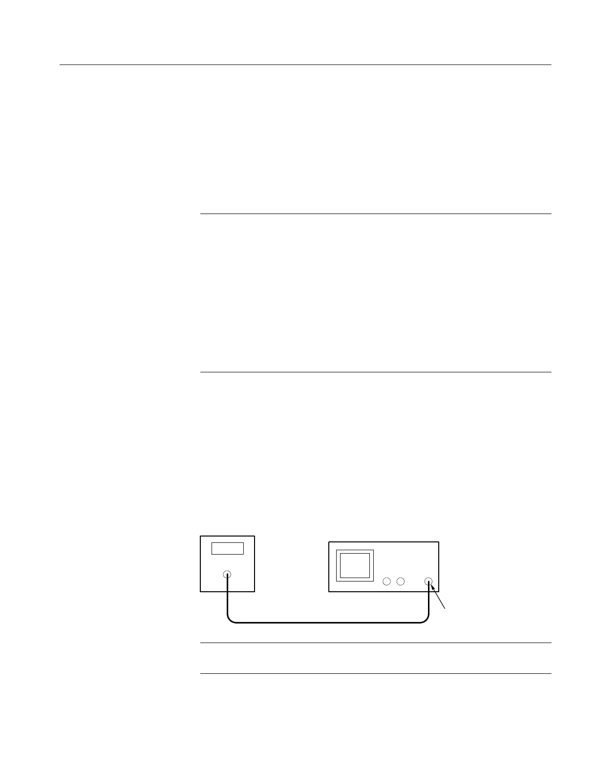
If you are adjusting a two-channel oscilloscope, a DC voltage needs to be
applied to the external trigger input. A typical on-screen instruction might read:
Apply --5.00 V DC signal to external trigger input.
When you see an instruction similar to this, connect the oscilloscope to the DC
voltage source and set the DC voltage to the specified value.
DC voltage
source
Ext Trig
Oscilloscope
NOTE. If the DC voltage source you are using has an output head, connect the
head directly to the external trigger input.
Applying Fast Rise Step
Signals to all Channels
Applying DC Voltage to
the External Trigger
 Loading...

