Portable Mainframe Removal and Installation Procedures
TLA7000 Series Mainframe Technical Reference Manual
7
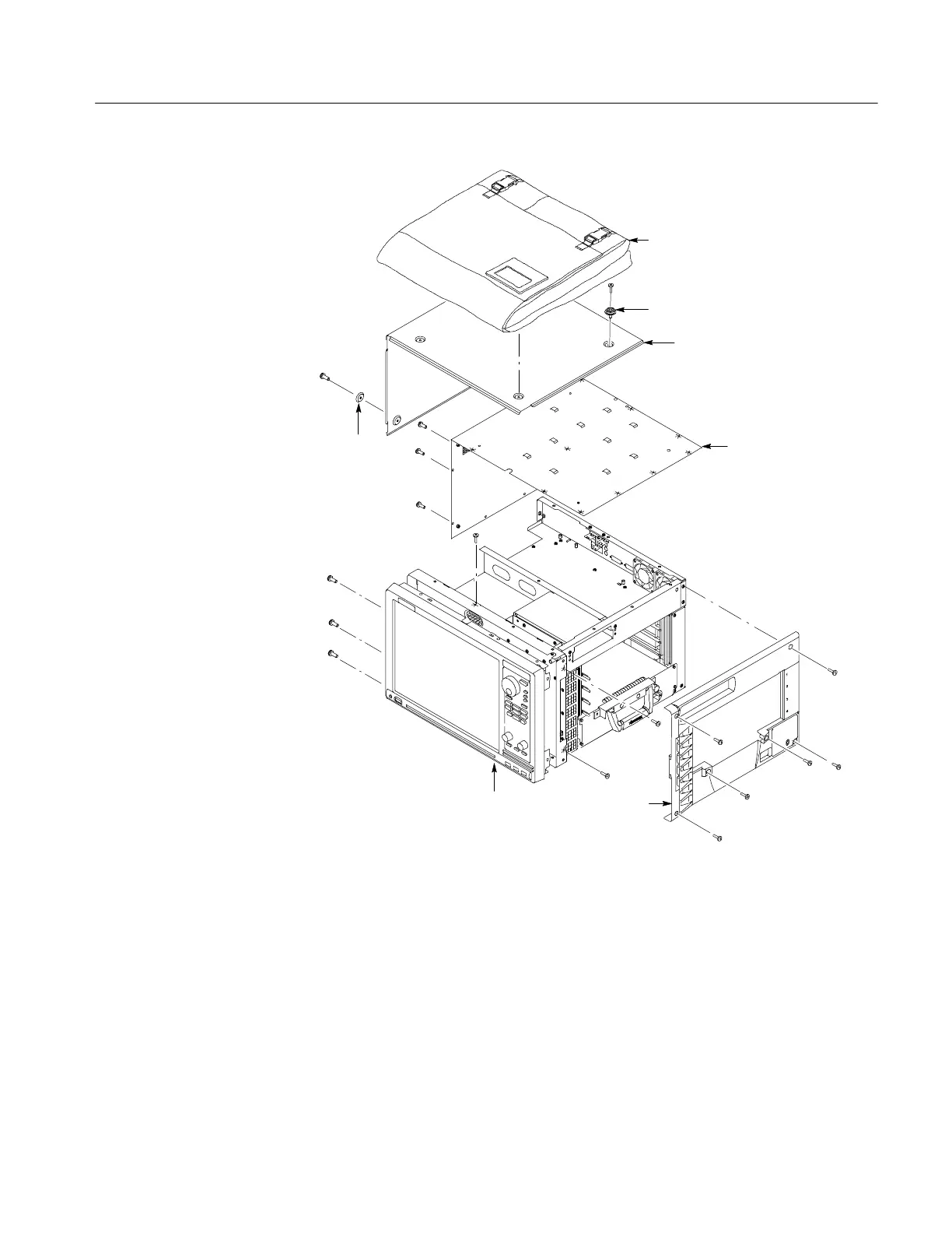
Pouch
Top cover
Top left
cover
Right side
cover
Front
panel/display
Snap
Skid foot
Figure 2: Instrument enclosure detail
5. Remove the accessory pouch and snap studs (4 T-15 screws).
6. Remove the four skid feet from the left side (4 T-15 screws).
7. Remove the remaining T-15 screws from the top left cover and then remove
the cover.
8. Set the instrument on the rear feet.

 Loading...


