Benchtop Mainframe Removal and Installation Procedures
28
TLA7000 Series Mainframe Technical Reference Manual
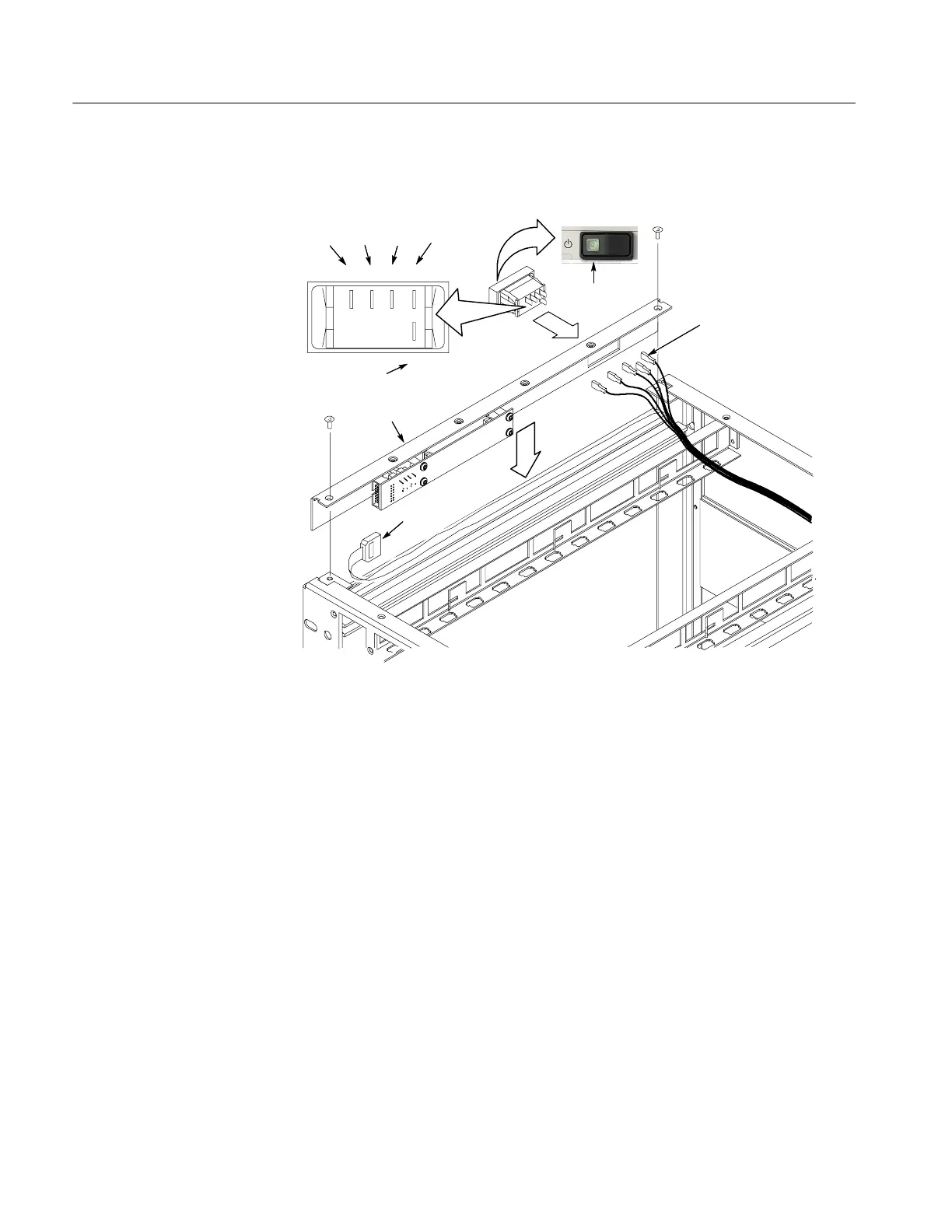
4. Connect the wires to the power switch as shown in Figure 18.
Green LED
on left side
1254
3
New front panel
Ribbon
cable
Five wires
Brown
Red Green Yellow
Orange
Figure 18: Installing the new front panel
5. Connect the ribbon cable from the mainframe to the front panel.
6. Position the front panel in the chassis. If there is a plastic cable retainer in
the way, remove it. Dress the ribbon cable around the display board to avoid
pinching the cable.
7. Dress the excess power switch cable towards the back of the chassis, away
from the card guides.
8. Attach one T-7 screw on each side of the front panel.
9. Replace the cover and partially install the side cover screws first, and then
the top screws, until the cover is aligned and all of the screws are started.
10. Tighten all of the cover screws.

 Loading...


