Portable Mainframe Removal and Installation Procedures
TLA7000 Series Mainframe Technical Reference Manual
13
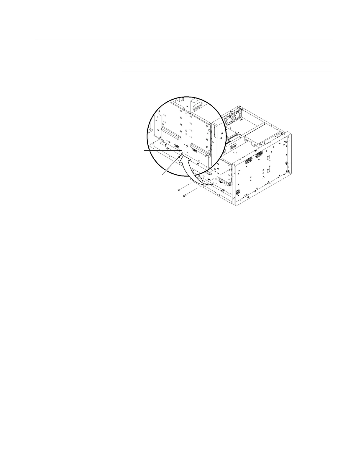
NOTE. When installing the binding posts, tighten them to 10 in-lbs.
Chassis post
Interface
board
Figure 8: Removing the backplane
Power Supply
Complete the following steps to remove the power supply. Refer to Figure 25 on
page 47 for the detailed exploded view drawings. Installation procedures are the
reverse of the removal procedures.
1. Remove the top and right plastic covers. (See Instrument Covers on
page 6.)
2. Remove bottom cover with the feet.
3. Remove the eight screws (four on the bottom EMI cover and four on the
side) securing the power supply to the chassis.
4. Pull out the assembly.
5. Remove the handle from the assembly.

 Loading...


