Getting Started
Probes
TPS2000B series oscilloscopes ship with TPP0101 or TPP0201 passive voltage
probes. (See page 10, Probe Safety.) (See page 123, TPS2000B Specifications.)
You can use many Tektronix voltage probes and current probes with these
oscilloscopes. Refer to Appendix C or the www.tektronix.com Web site for a list
of compatible probes.
Functiona
lCheck
Perform this functional check to verify that your oscilloscope is operating
correctly.
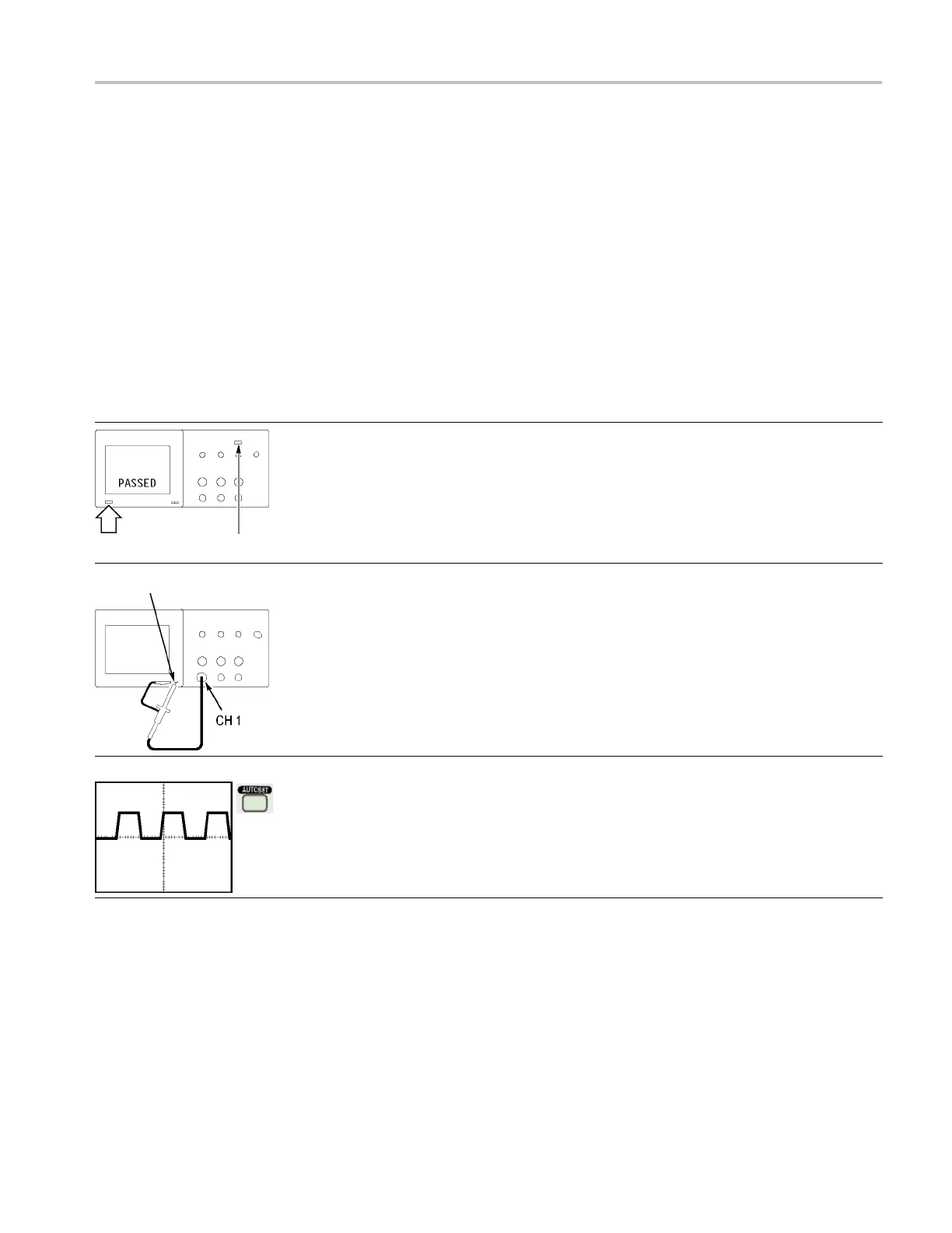
1. Power on the oscilloscope.
Push the Default Setup button.
The default Probe option attenuation setting is 10X.
On/Standby button Default Setup button
Probe Comp
2. Connect the probe to channel 1 o n the oscilloscope. To do this, align
the slot in the probe connector w ith the key on the channel 1 BNC,
push t
o connect, and twist to the right to lock the probe in place.
Connect the probe tip and reference lead to the Probe Comp terminals.
3. Push the AutoSet button. Within a few seconds, you should see a
squa
re wave in the display of about 5V peak-to-peak at 1 kHz.
Push the channel 1 Menu button on the front panel twice to remove
channel 1, push the channel 2 Menu button to display channel 2, and
rep
eat steps 2 and 3. For 4-channel models, repeat for channels 3
and 4.
TPS2000B Series Digital Oscilloscope User Manual 9