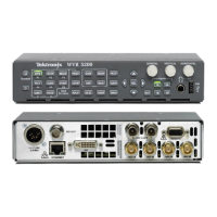
Getting Acquain
tedWithYourInstrument
Pin Pin Name Pin Pin Name
27
ANALOG_INPUT_B3_N
28
ANALOG_INPUT_A4_N
29
ANALOG_INPUT_B4_N
30
ANALOG_INPUT_A5_N
31
ANALOG_INPUT_B5_N
32
ANALOG_INPUT_A6_N
33
ANALOG_INPUT_B6_N
34
GND (Ground)
35
ANALOG_OUTPUT_1_N
36
ANALOG_OUTPUT_2_N
37
ANALOG_OUTPUT_3_N
38
ANALOG_OUTPUT_4_N
39
ANALOG_OUTPUT_5_N
40
ANALOG_OUTPUT_6_N
41
ANALOG_OUTPUT_7_N
42
ANALOG_OUTPUT_8_N
43
NC
44
NC
45
NC
46
NC
47
NC
48
NC
49
NC
50
NC
51
NC
52
NC
53
NC
54
NC
55
NC
56
NC
57
NC
58
NC
59
NC
60
NC
61
NC
62
NC
Connecting Signals. When connecting audio signals to the Analog Input connectors, you can use either balanced or
unbalanced signals. If you connect unbalanced signals to the inputs, you should connect the unbalanced output hot lead to
the balanced input positive pin and the unbalanced cold lead to the balanced input negative pin.
When connecting the Analog Output connectors, you can connect them as balanced or unbalanced. However, if you connect
the balanced outputs to an unbalanced input, you must ground the unused lead. You can ground either lead, but using the
negative output and grounding the positive output will effectively invert the phase.
NOTE. Note that grounding the unused lead does not attenuate the output but it does halve the clipping level. Therefore,
you must attenuate the output by at least 6 dB to avoid clipping. The output signal level in unbalanced mode is double
the signal level in balanced mode.
Units that have both analog and digital capability can have AES or embedded inputs converted to analog and then routed to
the eight balanced outputs.
Waveform Rasterizers Quick Start User Manual 19
 Loading...


