llI(lj.1~OMI't~~*llgliit.ll;l~eti~nl'(lmll!mrlllPi!~I~,.%~_1'.1 ••
j'-
It is possible to use the output of the courtesy light, to interface the control unit to an alarm system,
memorizing a radio alarm transmitter (code: TVSSH or TVTCTM) with mode 3 memorization and acti-
vating the "courtesy light as alarm" function (see 7.1).
If the control unit receives an alarm signal from the radio alarm transmitter, the courtesy light output is
activated for 1 minute.
Warning: the courtesy light output provides 230Vac. The interface of the alarm system must be ar-
ranged according to the specifications of the installed alarm system.
al
91 lliIl
ft
12 13 14
Alarm
interface
Alarm
system
Courtesy
light
&
With courtesy light set as alarm the flashing output
becomes the courtesy light output.
• Change the wire connection.
.l~!!I'~'!'$i1f0péiiitl~fiftlbde.·ii~è;ä1Tibren,ml.[~!
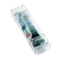
This procedure can be done within 30 seconds after the reset.
1- Press for 5 sec. the push release and re-press within 5 sec. the
button P3 of the transmitter; push button P3 of the transmitter 3
the buzzer will sound 1 beep, times, the buzzer wiJl sound 1 beep
at each pressure and at the end it wiJl
press 3 times
P3~
sound:
3 beeps to indicate ambient
light mode and
5 beeps to indicate alarm
function.
press and
h~df"::~
~ 5~:"
>
Beep
~
a. a. a.
Q) Q) Q)
Q) Q) Q)
mmm
123
wait 5 sec.
<,
/
3 Beeps: ambient light
5 Beeps: alarm function
Beeeeeep
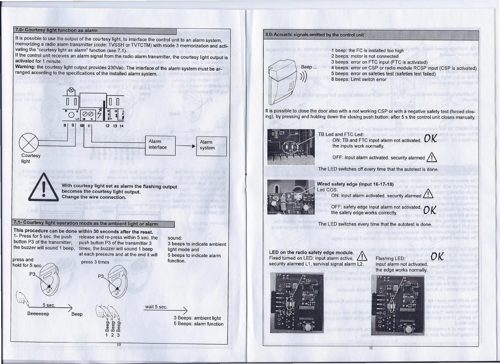
TB Led and FTC Led:
0"/
ON: TB and FTC input alarm not activated, I\..
the inputs work normally.
OFF: input alarm activated, security alarmed &
The LED switches
oft
every time that the autotest is done.
1
beep: the FC is insta lied toa high
2 beeps: motor is not connected
3 beeps: error on FTC input (FTC is ac!ivated)
4 beeps: error on CSP or radio module RCSP input (CSP is activated)
5
beeps: error on safeties test (safeties test failed)
8 beeps: Limit switch error
It is possible to do se the door also with a not working CSP or with a negative safety test (forced dos-
ing), by pressing and holding down the dosing push button; after 5 s the control unit doses manually.
Wired safety edge (input 16-17-18)
Led COS:
A
ON: input alarm activated, security alarmed
ill
OFF: safety edge input alarm not activated,
0
'
/
the safety edge works correctly. I\..
The LED switches every time that the autotest is done.
LED on the radio safety edge module.
A
Fixed turned on LED: input alarm active,
ill
security alarmed L1, survival signal alarm L2.
Flashing LED:
input alarm not activated,
the edge works normally.
OK
 Loading...