iRIS8 - Addressable Fire Alarm Panel – Installer Programming
17
3.2.1. Periphery Devices
All “functional modules” connected to the control panel configuration are defined as Periphery Devices, and have
special programming and settings. The Main board is not a periphery device.
Up to 12 periphery devices can be added to the system configuration of iRIS8 panel. The number and type of the
functional modules depend on the panel’s model.
Model and max. number of supported periphery devices
System name and description
OUT – Input / Output module
LOOP – Loop controller (expander)
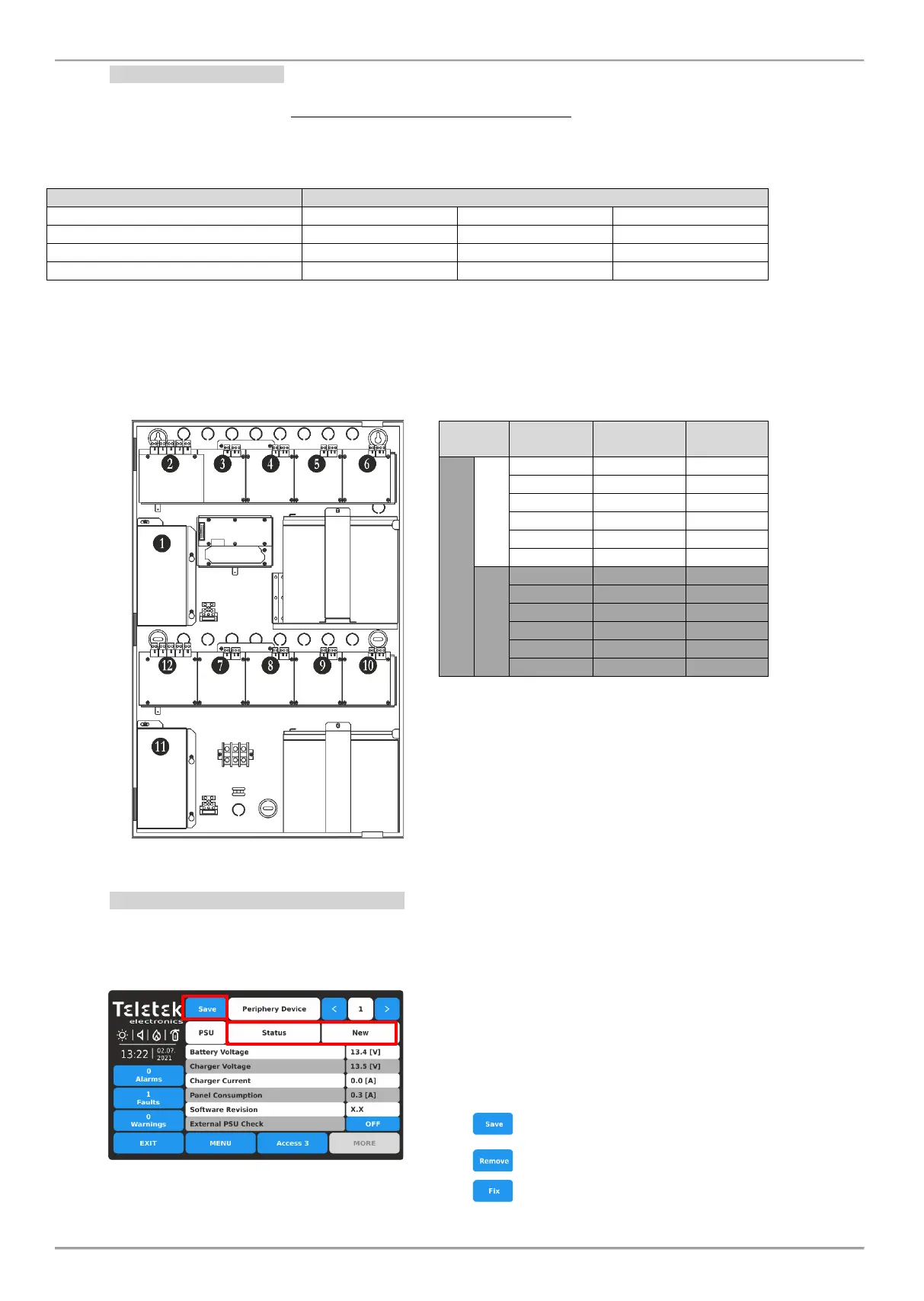
The periphery devices have factory set address numbers that cannot be changed. The following diagram shows the
position and the set factory addresses. The loop controllers always take addresses from 3 to 10.
The following drawing of the hardware configuration of iRIS8 panel models and table represent the fixed factory
addresses of the periphery devices, which must be assumed during the initial power up and programming of the whole
system.
The free addresses for periphery devices are
presented as EMPTY.
3.2.2. Current Status of Periphery Device
Enter PERIPHERY menu.
The available periphery devices can be reviewed one-by-
one at the top of the screen using the arrows next to the
Periphery Device field. The order and type of the devices
is displayed on the table above.
The current status of periphery device is presented on the
second row.
According the current status (NEW, FAULT, TYPE
ERROR), at the upper left corner of the screen is
displayed a button with specific functionality:
- Add the new found device to the system
configuration
- Delete the device from the system configuration
- Different type of device is detected