iRIS8 - Addressable Fire Alarm Panel – Installer Programming
19
3.2.4. Input-Output Module Screen
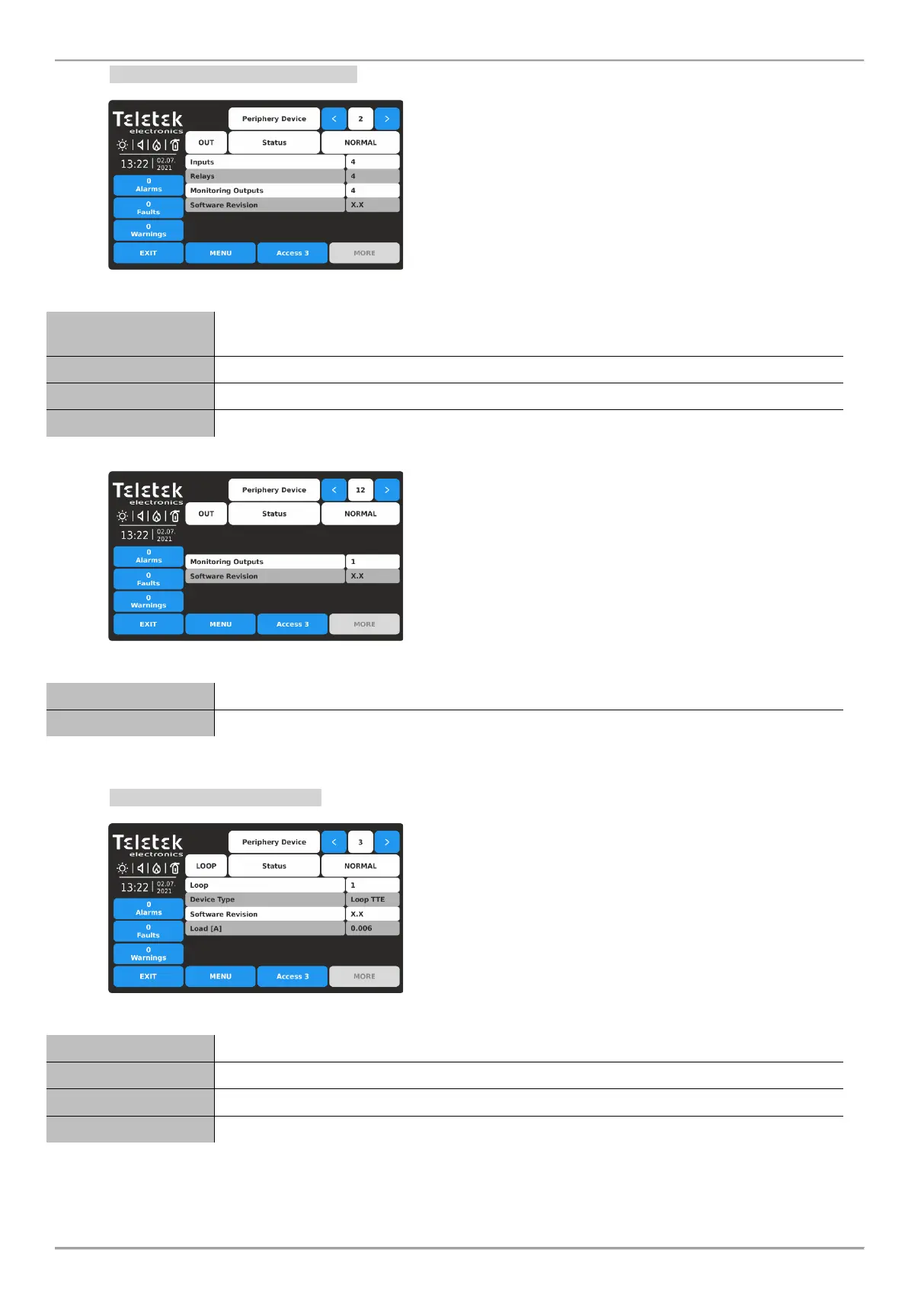
At ADDRESS 2 is presented information about the input-
output module (OUT1) connected to first main power
supply.
The screen displays the hardware capability of the
module – the number of available inputs and outputs.
The OUT1 input-output module has the following hardware resources:
4 Monitoring inputs: Protection Confirmation, Fault Protection, Alarm Confirmation, Fire
Protection (VdS 2540).
4 Programmable relay outputs 10A@24V DC.
4 Monitored outputs: Sounder, Fire Protection, Fire, Fault.
Software version of the input-output module.
At ADDRESS 12 is presented information about the
output module (OUT2) connected to second main power
supply.
The OUT2 output module has the following hardware resources:
1 Monitored output: Sounder.
Software version of the output module.
3.2.5. Loop Controller Screen
The loop controllers always take consequent addresses
from 3 to 10. The address number is added automatically
and its number depends on the hardware configuration of
the panel.
At the Loop parameters screen the installer can review the following information:
Address number of the loop in the hardware configuration of the system.
Type of the communication protocol.
Software version of the loop controller.
Current consumption in the loop.