iRIS8 - Addressable Fire Alarm Panel – Installer Programming
24
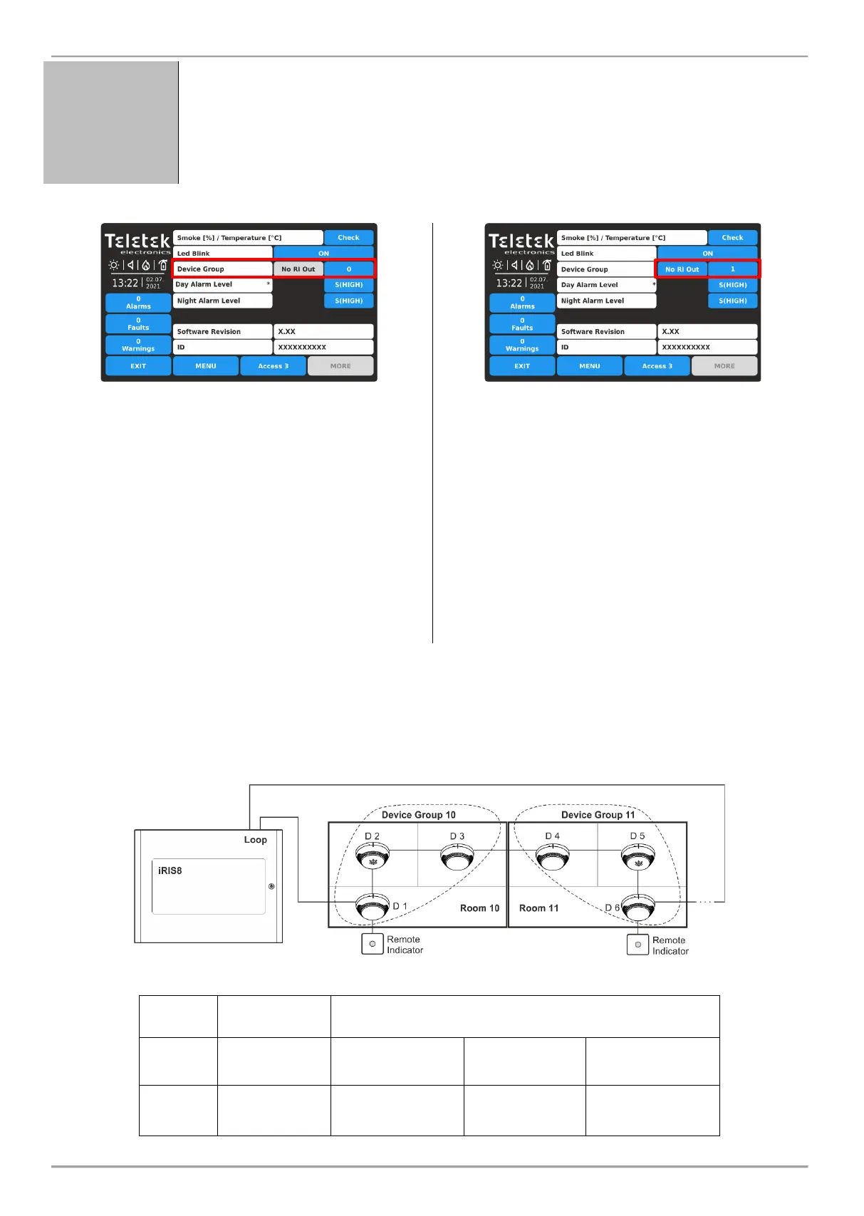
Setting a Device Group number for controlling a LED remote indicator (RI).
The RI control option gives the installer possibility to use one LED remote indicator for up to
100 separate detectors without using additional cabling. The installer has to set a group
number for the detector with the physical connection to the remote indicator (RI) and then to
associate to that same group other detectors from the loop. Thus, every detector
associated to the group in case of fire alarm condition can activate the remote indicator
although it is not physically connected with it.
This is a field for entering a group number (from 1 to 100)
for the detector. In case of a fire alarm, the detector will
activate the RI for that group number. Set “0” if no device
group for RI control is applicable or required for the
detector – the RI OUT option is unavailable.
In a device group can be included one or more other
detectors for controlling a single remote indicator. This
option is called RI control.
Note: The RI Output is the terminal “4” on the SensoIRIS
B124 standard fire bases used for installation of
SensoIRIS fire alarm detectors. For details on hardware
connection and installation refer to the installation manuals
of SensoIRIS B124 standard base and the SensoIRIS
detectors series.
When a Device Group Number is set (1-100) the RI OUT
option is available to change as every pressing of the
button will alternatively change the status:
NO RI OUT – The operation of the RI Output of the
detector is not controlled (activated) from the set Device
Group. That means, if a remote indicator is connected to
the detector’s output, then it will operate individually it will
be activated only from the detector(s) to which is
physically connected. Use that setting and for those
cases when there is no RI connected to the detector’s
output.
RI OUTPUT – The operation of the RI Output of the
detector is controlled (activated) from the set Device
Group.
Example using the RI functionality:
Rooms 10 and 11 are separate apartments in a hotel. All detectors installed in Room 10 are associated to Device Group
10 and all of them can activate the Remote Indicator physically connected only to Detector 1.
All detectors installed in Room 11 are associated to Device Group 11 and all of them can activate the Remote Indicator
physically connected only to Detector 6.
Panel Settings
(Device GROUP section)
D 1:
Device Group: 10
RI OUTPUT set
D 2:
Device Group: 10
No RI OUT
D 3:
Device Group: 10
No RI OUT
D 4:
Device Group: 11
No RI OUT
D 5:
Device Group: 11
No RI OUT
D 6:
Device Group: 11
RI OUTPUT set