ME910C1 mPCIe HW Design Guide
1VV0301642 Rev. 2 Page 13 of 56 2022-01-14
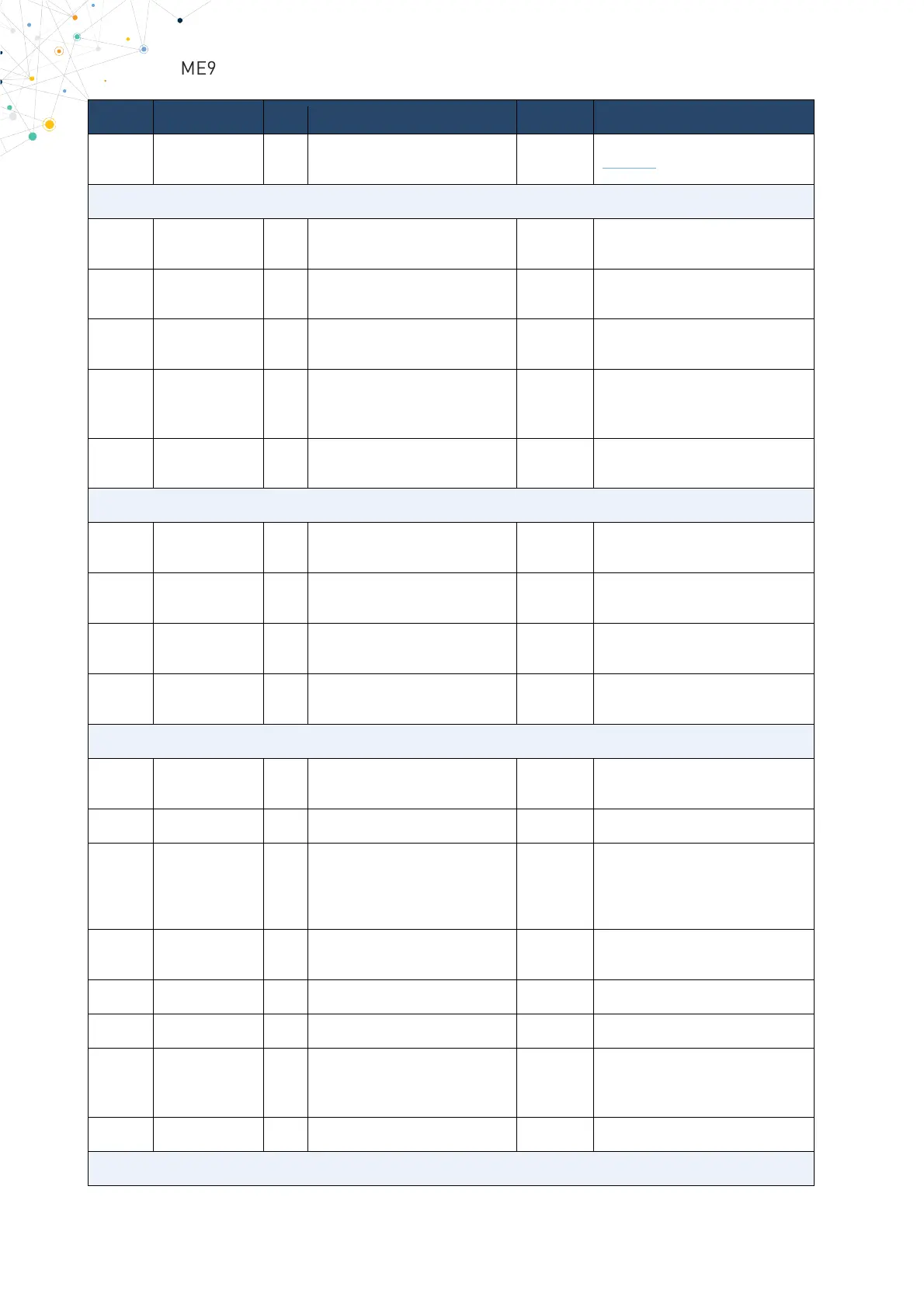
UART_CTS I
Input for Clear To Send signal
1.8V See note
I2S – Digital Voice Interface (DVI)
PCM_CLK I/O
Digital Audio Interface (BIT
Clock)
1.8V
Only for ME910G1-WW
RESERVED for others
PCM_TX O
Digital Audio Interface (TX Out
1.8V
Only for ME910G1-WW
PCM_RX I
Digital Audio Interface (RX Into
the card)
1.8V
Only for ME910G1-WW
RESERVED for others
PCM_SYNC I/O
(Frame_Sync)
1.8V
Only for ME910G1-WW
RESERVED for others
REF_CLK O
Reference clock for external
Codec
1.8V Reserved
SIMVCC I/O
External SIM signal
1.8 / 3V
SIMIO I/O
External SIM signal
1.8 / 3V
SIMCLK O
External SIM signal
1.8 / 3V
SIMRST O
External SIM signal
Reset
1.8 / 3V
WAKE_N O
Active Low output signal Wake
Up signal to the host system
3V3_AUX
1V5 O 1V5 Power Supply Power Not Used
W_DISABLE_N I
· Shutdowns
· Wireless disabling (Flight
3V3_AUX
Already has an internal 100K PU
to 3V3_AUX
PERST_N I
Active Low Input Signal
3V3_AUX
Should be externally
3V3 - 3.3V Digital Power Supply Power Not Used
LED_WWAN_N O
Open Drain circuitry
LED driving, for module’s
status indication
LED should be PU externally in
series to 3V3_AUX