ME910C1 mPCIe HW Design Guide
1VV0301642 Rev. 2 Page 29 of 56 2022-01-14
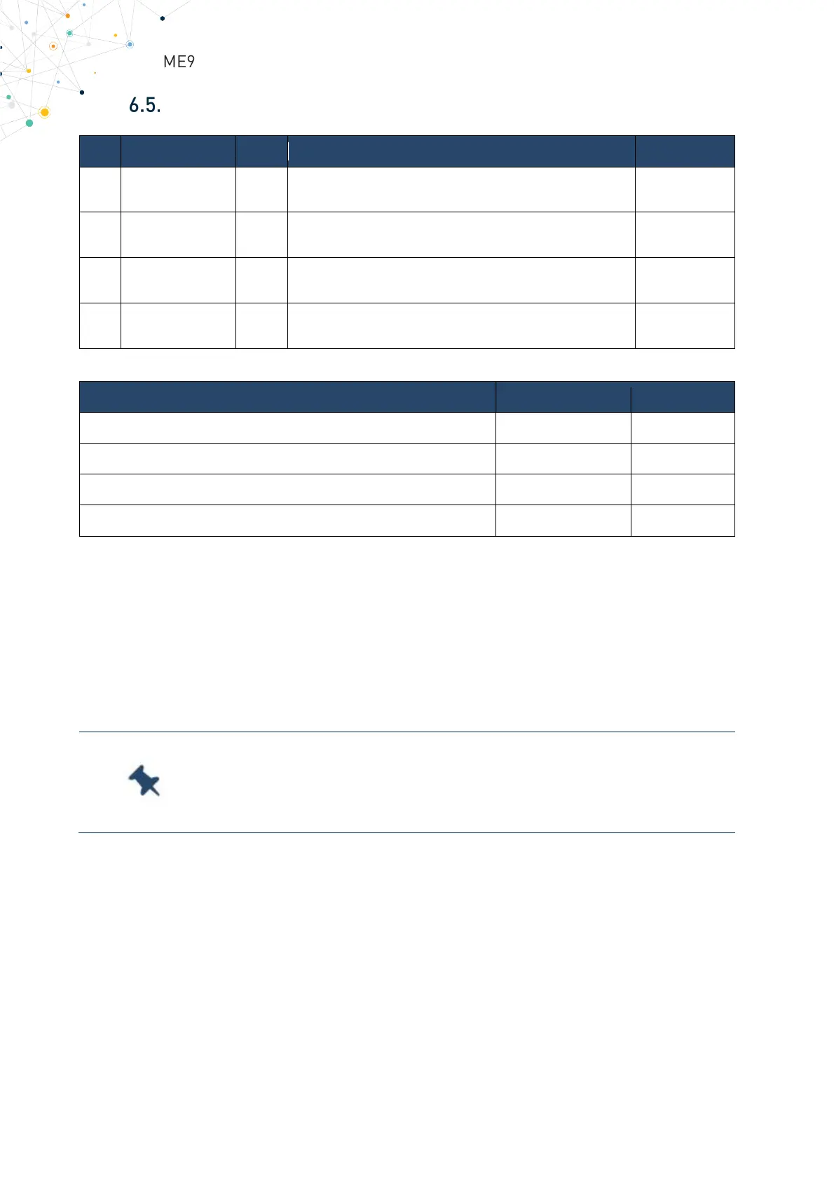
Control Signals
WAKE_N O Open Drain Output Signal
Wake Up signal to the host
3V3_AUX
Active Low Input Signal Shutdown
Wireless disabling (Airplane mode)
PERST_N I Active Low Input Signal
3V3_AUX
LED_WWAN_N O Open Drain Output Signal
LED driving, for module’s status indication
3V3_AUX
Table 15 Control signals
2.0
3V3_AUX
-0.5V 0.8V
Table 16 Control signal operating levels
6.5.1. W_DISABLE_N and PERST_N
W_DISABLE_N and PERST_N are both used for unconditionally shutdown the mPCIe.
Whenever one of these signals is pulled low, the module shutdowns. After releasing both
signals the module restarts. The module has already an internal Power On Reset control
and do not need other external componets.
Do not use W_DISABLE_N and PERST_N to power cycle without
first preparing the module to shutdown.
Read more at chapter §6.4 Power OFF Procedure.
6.5.2. LED_WWAN_N
LED_WWAN_N is driven by the module according the PCI Express Mini Card
Electromechanical Specification Revision 2.1. If desired, LED behavior can be configured
by adjusting software settings [2][6]. The LED circuit driver is in an Open Drain
configuration. LED can be directly connected to LED_WWAN_N through a PU series
resistor to 3V3_AUX.