ME910C1 mPCIe HW Design Guide
1VV0301642 Rev. 2 Page 31 of 56 2022-01-14
Even if USB
communication is not used, it is still highly
recommended to place an optional USB connector on the application
board. At least test points of the USB signals are required since the
USB physical communication is needed in case of SW update.
6.6.2. Serial Port
The serial port is typically a secondary interface between the ME910X1-mPCIe module
and OEM hardware.
Several configurations can be designed for the serial port on the OEM hardware.
The most common configurations are:
• RS232 PC com port
• Microcontroller UART
Depending on the serial port interfaces on the OEM hardware, you will need an extra
components for voltage level translation. It is important to satisfy the condition in which
during Shutdown, OFF or Power cycling, any external signals should be floating to avoid
module’s latchup and damage.
When mPCIe UART is directly connetd to a PC an RS232 translator is necessary, see more
details in §6.6.2.1 RS232 Level Translator
The levels for the UART are CMOS 1.8V as described in §6.1 Logic Levels
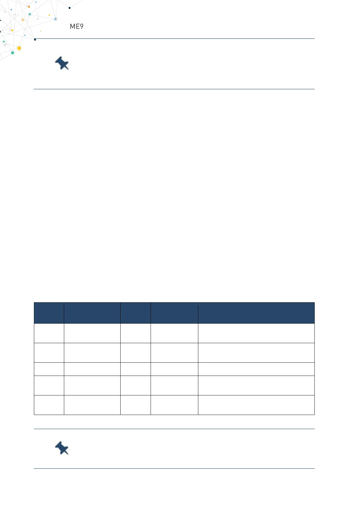
List of the signal interconnections between RS232 and UART in the ME910X1-mPCIe:
RS232
Signal
mPCIe
UART Function
Notes
RXD <-> UART_TX 5 Transmit Line ME910X1-mPCIe UART
ME910X1-mPCIe UART
Input receive line
GND 4,9,15…. Ground Ground
RTS <-> UART_CTS 19 Request to Send ME910X1-mPCIe UART
Input controlling the Hardware flow control
ME910X1-mPCIe UART
Output controlling the Hardware flow control
Table 19 Modem Serial Port 1 Signals
To avoid a back-powering effect, it is recommended to prevent
any High logic level signal from being applied to the digital pins of the
module when it shutdowns, during OFF or Power Cycling.