ME910C1 mPCIe HW Design Guide
1VV0301642 Rev. 2 Page 17 of 56 2022-01-14
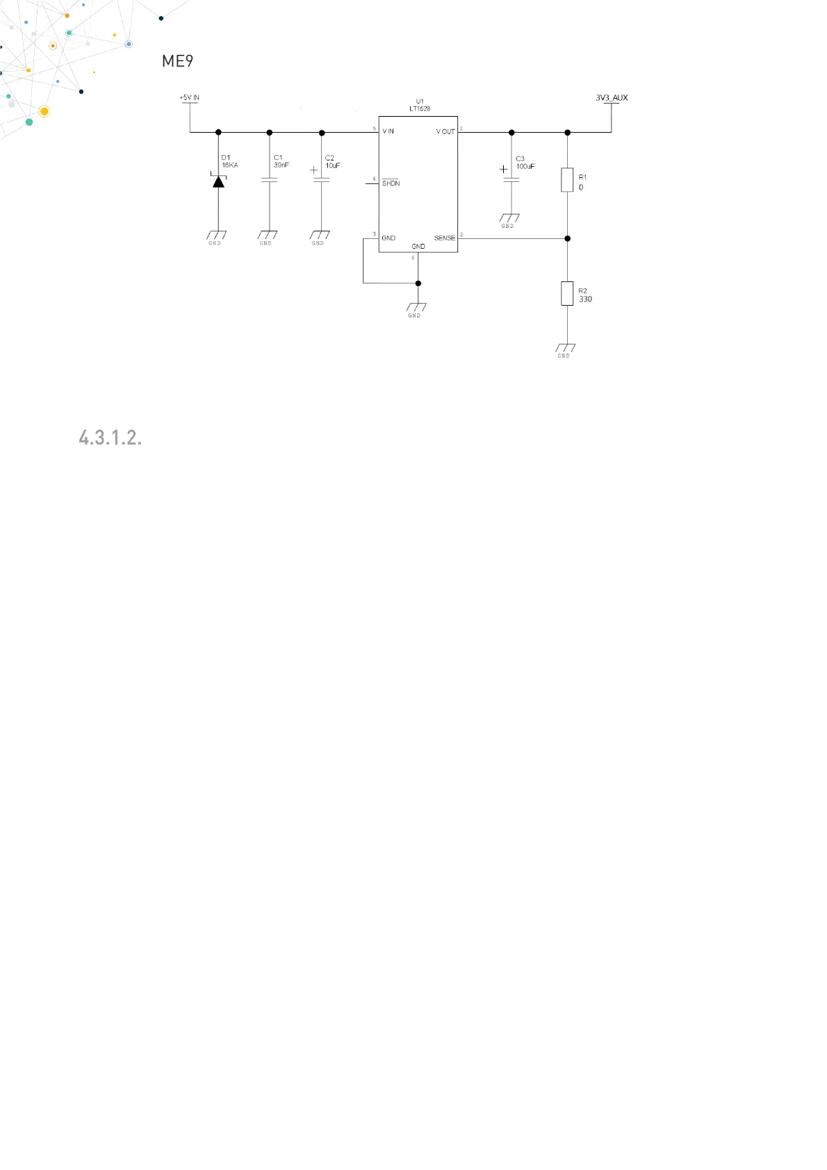
Figure 1: Linear regulator with 5V input and 3.3V output
+12V Source Power Supply Design Guidelines
• The desired output for the power supply is 3.3V. Due to the large difference
between the input and output voltage values together with the current sinked,
the linear regulator in the example above is capable but not efficient at high
current sink and should not be used. A switching power supply will be
preferable due to its better efficiency.
• When using a switching regulator, a 500kHz or more switching frequency
regulator is preferable because of its smaller inductor size and its faster
transient response. This allows the regulator to respond quickly to the current
peaks absorption.
• In any case the frequency and Switching design selection is related to the
application to be developed since the switching frequency could also generate
EMC interferences.
• For car PB battery the input voltage can rise up to 15.8V and this should be kept
in mind when choosing components: all components in the power supply must
withstand this voltage.
• A Bypass low ESR capacitor of adequate capacity must be provided in order to
cut the current absorption peaks, a 100μF capacitor is usually suitable.
• Make sure the low ESR capacitor on the power supply output is rated at least
10V.
• For Car applications, a spike protection diode should be inserted close to the
power input, in order to clean the supply from spikes.